


202 CHAPTER 16: CONFIGURING LAPB AND X.25
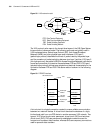
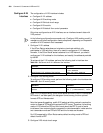
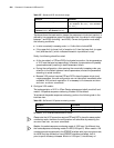
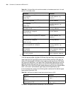
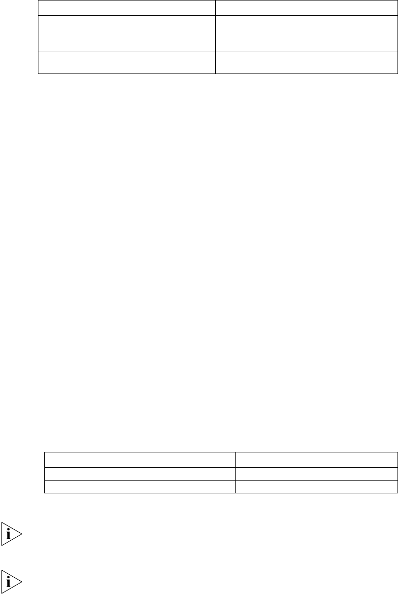
Table 237 Set/cancel X.25 virtual circuit range
The above shows that each section (except the permanent virtual circuit section) is
defined by two parameters: upper limit and lower limit, the value of which ranges
between 1 and 4095 (including 1 and 4095). Correct configuration must satisfy
the following conditions:
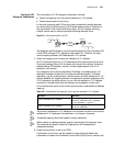
■ In strict numerically increasing order, i.e. 1lichic<ltchtc<lochoc4095.
■ If the upper limit (or lower limit) of a section is 0, then the lower limit (or upper
limit) shall also be 0, (which indicates this section is prohibited to use).
Finally, the following should be noted:
■ At the two sides (i.e. DTE and DCE) of a physical connection, the six parameters
of X.25 must be equal correspondingly, otherwise, the procedure will possibly
operate abnormally, resulting in data transmission failure.
■ During the configuration, after ensuring the numerically increasing order, pay
attention to the default values of various parameters, and set the parameters
according to actual condition.
■ Because X.25 protocol requires DTE and DCE to have the same virtual circuit
range parameters, the new configuration can not take effect immediately after
successful X.25 protocol negotiation. It is necessary to first execute
shutdown
and
undo shutdown commands.
4 Configure X.25 modulo
The implementation of X.25 in 3Com Router series supports both modulo 8 and
modulo 128 packet sequence numbering. Module 8 is the default.
To set/cancel the packet sequence numbering, perform the following task in the
interface view:
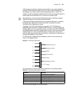
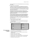
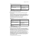
Table 238 Set/Cancel X.25 packet numbering modulo
By default, X.25 interface use modulo 8 mode.
Please note that X.25 procedure requires DTE and DCE to have the same packet
numbering mode, therefore the configuration will take effect by executing the
shutdown and undo shutdown commands.
Besides, the packet sequence numbering mode of X.25 layer 3 is different from
the frame sequence numbering mode of LAPB (X.25 layer 2). When modulo 128
numbering mode is employed in the DTE/DCE interface with high throughput rate,
for LAPB, only the efficiency of local DTE/DCE interface is affected, that is
point-to-point efficiency increases. While for X.25 layer 3, the efficiency of
Operation Command
Set X.25 virtual circuit range x25 vc-range { in-channel hic lic
| bi-channel htc ltc | out-channel
hoc loc }
Cancel the set vc-range { in-channel hic lic |
bi-channel htc ltc | out-channel hoc loc }
undo x25 vc-range
Operation Command
Set the packet sequence numbering mode x25 modulo { 8 | 128 }
Cancel the set packet sequence numbering mode undo x25 modulo