196 CHAPTER 16: CONFIGURING LAPB AND X.25
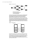
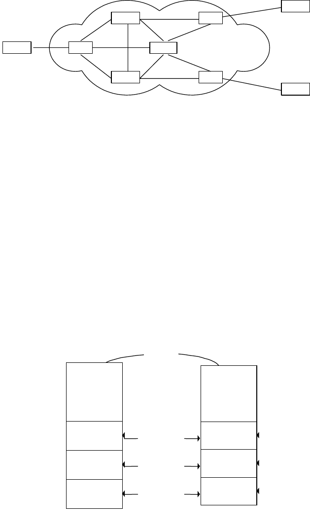
Figure 58 X.25 network model
The X.25 protocol suite maps to the lowest three layers of the OSI (Open System
Interconnection) reference model. The following protocols are typically used in
X.25 implementations: Packet-Layer Protocol (PLP), Link Access Procedure
Balanced (LAPB), and other physical-layer serial interfaces. X.25 layer 3
(packet-layer protocol) describes the format of packet used by the packet layer
and the procedure of packet switching between two layer 3 entities. X.25 layer 2
(link-layer protocol), also called LAPB (Link Access Procedure Balanced), defines the
format and procedure of interactive frames between DTE and DCE. X.25 layer 1
(physical-layer protocol) defines some physical and electrical characteristics in the
connection between DTE and DCE. The above relation is shown in the following
diagram.
Figure 59 DTE/DCE interface
A virtual circuit is a logical connection created to ensure reliable communication
between two network devices. A virtual circuit denotes the existence of a logic,
bi-directional path from one DTE device to another across an X.25 network. Two
types of X.25 virtual circuits exist: permanent virtual circuit (PVC) and switched
virtual circuit (SVC). PVCs are permanently established connections used for
frequent and consistent data transfers, whereas SVCs are temporary connections
used for sporadic data transfers.
DCEDTE
DCE
DCE
DTE
DTE
PSE
PSE
PSE
PSN
DTE: Data Terminal Equipment
DCE: Data Circuit-terminating Equipment
PSE: Packet Switching Equipment
PSN: Packet Switching Network
OSI reference model
7
6
5
4
3
2
1
X.25
Packet layer
interface
Link layer
interface
Physical layer
interface
DTE
DCE
X.25
Physical layer
X.25
Link layer
X.25
Packet layer
X.25
Physical layer
X.25
Link layer
X.25
Packet layer


