


Configure Frame Relay 251
The map created through the dynamic inverse ARP has broadcast attribute.
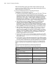
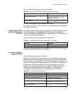
6 Configure Frame Relay Local Virtual Circuit Number
Perform the following configurations in synchronous serial interface view.
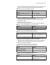
Table 281 Configure Frame Relay local virtual circuit number
After entering the DLCI view through the fr dlci command, the user can
configure the parameters associated with this virtual circuit, such as Frame Relay
class.
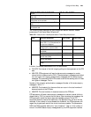
The virtual circuit number is valid locally, that is, the virtual circuit numbers on both
ends of the link can be the same. Different interfaces can be assigned with the
same virtual circuit number, but the virtual circuit number must be unique on one
physical interface.
When the Frame Relay interface type is DCE or NNI, the interface (either main
interface or sub-interface) should be configured manully with virtual circuits.
When the Frame Relay interface type is DTE, for the main interface, the system will
determine the virtual circuit automatically according to the opposite equipment;
the sub-interface must be configured with virtual circuits manually.
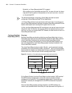
7 Configure Frame Relay Sub-Interface
The Frame Relay interface is a kind of NBMA (Non-Broadcast Multi-Access)
interface, which supports sub-interfaces. The Frame Relay module has two types
of interfaces: main interface and sub-interface. The sub-interface is logical
interface and can be used to configure protocol address and virtual circuit. One
physical interface can include multiple sub-interfaces, which do not exist
physically. However, for the network layer, both the sub-interface and main
interface can be used to configure the virtual circuit to connect to remote
equipment.
The sub-interfaces of Frame Relay fall into two types: point-to-point sub-interface,
used to connect a single remote object and point-to-multipoint sub-interface,
used to connect multiple remote objects in the same network segment.
The address mapping relation between the frame-relay sub-interfaces can be
configured manually, or dynamically established by using the inverse ARP. For a
point-to-point sub-interface, you only need configure one PVC on this
sub-interface, since there is only one peer device. For a point-to-multipoint
sub-interface, you can configure multiple PVCs. Each PVC can establish the
address mapping with its connected peer through running the inverse dynamic
ARP. Thereby, different PVCs can reach their peers without confusing.
Alternatively, you can respectively establish different static address mapping for
these PVCs.
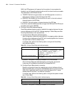
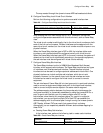
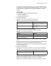
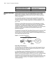
a Creating Frame Relay Sub-Interface
In the interface view, perform the following task to create a sub-interface.
Table 282 Create Frame Relay sub-interface
Operation Command
Assign a virtual circuit number to Frame Relay interface fr dlci dlci-number
Remove the virtual circuit number of Frame Relay
interface
undo fr dlci dlci-number
Operation Command
Enter interface view interface type number