658 CHAPTER 46: CONFIGURING VRRP
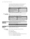
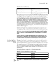
Table 710 Display and Debug VRRP
VRRP Configuration
Examples
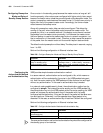
This section describes several different configurations of VRRP with a suggested
procedure for each configuration
VRRP Single Standby
Group
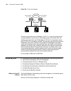
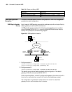
Host A uses the VRRP standby group which combines router A and router B as its
default gateway to visit host B on the Internet.
A VRRP standby group consists of the following parts: standby group number1,
virtual IP address 202.38.160.111, router A as the MASTER and router B as the
backup with preemption a
II. Networking diagram
Figure 209 VRRP application illustration
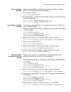
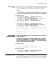
1 Configure router A:
[Router-Ethernet0] vrrp vrid 1 virtual-ip 202.38.160.111
[Router-Ethernet0] vrrp vrid 1 priority 120
2 Configure router B:
[Router-Ethernet0] vrrp vrid 1 virtual-ip 202.38.160.111
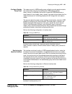
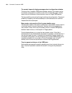
The standby group can be used immediately after configuration. The default
gateway of host A can be set as 202.38.160.111.
Under normal conditions, router A functions as the gateway, but when router A is
turned off or malfunctioning, router B will function as the gateway instead.
The configuration of preemption mode is aimed for router A to resume its
gateway function as the master when it recovers.
Operation Command
Display VRRP State Information display vrrp
Enable the debugging of VRRP debugging vrrp { packet | state }
Host B
10.2.3.1
Host A
202.38.160.1 202.38.160.2
Visual IP address
202.38.160.111
202.38.160.3
Router A Router B
Internet


