


618 CHAPTER 43: CONFIGURING L2TP
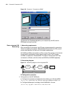
II. Networking diagram
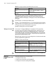
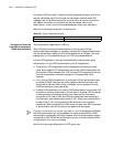
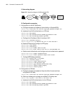
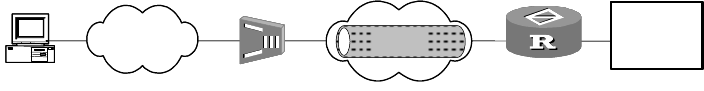
Figure 183 Networking diagram of NAS-originated VPN
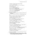
III. Configuration procedure
1 Configuration at the LAC (NAS) side:)
a Configure username and password (when dialing in Windows2000).
[Router-LAC] local-user lac service-type ppp password simple lac
b Implement local AAA authentication on VPN user.
[Router-LAC] aaa-enable
[Router-LAC] aaa authentication-scheme ppp default local
[Router-LAC] aaa accounting-scheme optional
c Configure the IP address of Serial1 interface of LAC.
[Router-LAC] interface serial 1
[Router-LAC-Serial1] ip address 192.167.0.2 255.255.255.0
d Enable L2TP service and configure a L2TP group.
[Router-LAC] l2tp enable
[Router-LAC] l2tp-group 1
[Router-LAC-l2tp1] tunnel name lac-end
[Router-LAC-l2tp1] start l2tp ip 192.167.0.1 fullusername lac
e Enable tunnel authentication and configure a tunnel authentication password.
[Router-LAC-l2tp1] tunnel authentication
[Router-LAC-l2tp1] tunnel password simple 3Com router
f Configure BDR dialup parameters.
[Router-LAC] dialer-rule 1 ip permit
[Router-LAC] interface async 2
[Router-LAC-Async2] async mode protocol
[Router-LAC-Async2] link-protocol ppp
[Router-LAC-Async2] ppp authentication-mode chap
[Router-LAC-Async2] dialer enable-legacy
[Router-LAC-Async2] dialer-group 1
2 Configuration at LNS side
a Configure username and password (they should be the same as those
configured at LAC side)
[Router-LNS] local-user lac service-type ppp password simple lac
b Define an address pool and assign an address for the dialup user.
[Router-LNS] ip pool 1 192.168.0.3 192.168.0.100
c Implement local AAA authentication for the VPN user.
[Router-LNS] aaa-enable
[Router-LNS] aaa authentication-scheme ppp default local
[Router-LNS] aaa accounting-scheme optional
VPN
User
PSTN/ISDN
Company
headquarters
LAC
Internet
LNS
tunnel
NAS
S1
S0
Async2
VPN
User
PSTN/ISDN
Company
headquarters
LAC
Internet
LNS
tunnel
NAS
S1
S0
Async2