


Typical Frame Relay Configuration Example 277
[Router-Serial1] ip address 202.38.163.253 255.255.255.0
b Configure the link layer protocol of the interface to Frame Relay
[Router-Serial1]link-protocol fr
[Router-Serial1]fr interface-type dte
c Configure static address mapping
[Router-Serial1]fr map ip 202.38.163.251 dlci 80
Interconnect LANs via
Private Line
I. Networking Requirement
Two Routers are directly connected via a serial port. Router A works in the Frame
Relay DCE mode, and Router B works in the Frame Relay DTE mode. The router
use dynamic address mapping.
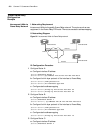
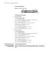
II. Networking Diagram
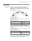
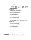
Figure 93 Interconnect LANs via private line
III. Configuration Procedure
1 Configure Router A:
a Configure interface IP address
[Router]interface serial 1
[Router-Serial1]ip address 202.38.163.251 255.255.255.0
b Configure the link layer protocol of the interface to Frame Relay
[Router-Serial1]link-protocol fr
[Router-Serial1]fr interface-type dce
c Configure local virtual circuit
[Router-Serial1]fr dlci 100
2 Configure Router B:
a Configure interface IP address
[Router]interface serial 1
[Router-Serial1]ip address 202.38.163.252 255.255.255.0
b Configure the link layer protocol of the interface to Frame Relay
[Router-Serial1]link-protocol fr
[Router-Serial1]fr interface-type dte
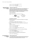
Connect Routers
through Multilink Frame
Relay (FRF.16)
I. Networking Requirements
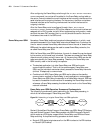
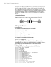
RouterA and RouterB are directly connected via the serial ports Serial 0 and Serial1
and through Frame Relay protocol. The two serial ports are bundled together to
provide wider bandwidth.
IP:202.38.163.251 IP:202.38.163.252
DLCI=100
Router A Router B