Typical DLSw Configuration Example 397
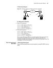
II. Networking Diagram
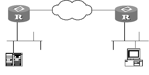
Figure 139 Networking diagram of DLSw configuration of LAN-LAN
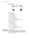
III. Configuration Procedure
1 Router A Configuration:
[Router] dlsw local 10.120.25.1
[Router] dlsw remote 10.120.5.2
[Router] dlsw bridge-set 5
[Router] interface ethernet 0
[Router-Ethernet0] bridge-set 5
2 Router B Configuration:
[Router] dlsw local 10.120.5.2
[Router] dlsw remote 10.120.25.1
[Router] dlsw bridge-set 7
[Router] interface ethernet 0
[Router-Ethernet0] bridge-set 7
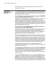
Thus, the two LANs across WAN are connected together. Note that we don't list
the related IP commands here, but you have to make sure that IPs of the
configured local-peer and remote-peer can be intercommunicated each other. The
notes apply for the following sections.
DLSw Configuration of
SDLC-SDLC
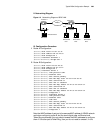
I. Networking Requirement
The two SDLCs across WAN are connected together by using SDLC-SDLC working
mode.
EthernetEthernet
Router A
LLC2
IBM AS/400 PC(SNA)
WAN(IP)
Router B
LLC2
10.120.25.1
10.120.5.2


