


Typical Frame Relay Configuration Example 279
II. Networking Diagram
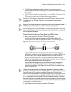
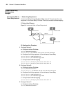
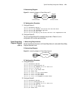
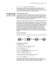
Figure 95 networking diagram of Frame Relay over IP
III. Configuration Procedure
1 Configure Router A
[Router]interface serial 0
[Router-Serial0]ip address 202.38.163.251 255.255.255.0
[Router-Serial0]fr interface-type dte
[Router-Serial0]fr dlci 100
[Router-Serial0]fr map ip 202.38.163.252 dlci 100 compression frf9
2 Configure Router B
You can configure Router B in the same way as that of Router A, so its
configuration will not be mentioned here.
Typical Frame Relay
Fragment Example
(FRF.12)
I. Networking Requirements
RouterA and Router B connect with Frame Relay Network. and enable Frame Relay
Fragment between them.
II. Networking Diagram
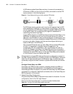
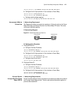
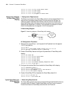
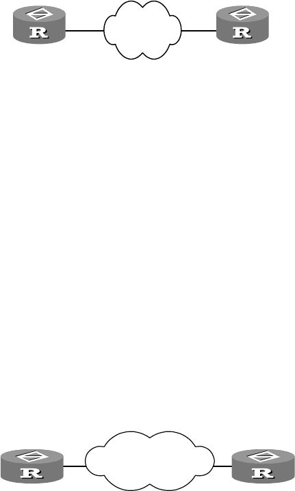
Figure 96 networking diagram of Frame Relay Fragment
III. Configuration Procedure
1 Configure RouterA
[Router]interface serial0
[Router-Serial0]link-protocol fr
[Router-Serial0]ip address 10.1.1.2 255.0.0.0
[Router-Serial0] fr dlci 16
[Router-fr-dlci-16]fr-class frts
[Router]fr class frts
[Router-fr-class-frts]cir allow 64000
[Router-fr-class-frts]cbs 64000
[Router-fr-class-frts]cir 64000
[Router-fr-class-frts]fragment 80 data-level
2 Configure RouterB
[Router]interface serial0
[Router-Serial0]link-protocol fr
[Router-Serial0]ip address 10.1.1.1 255.0.0.0
[Router-Serial0]fr dlci 16
[Router-fr-dlci-16]fr-class frts
[Router]fr class frts
IP:202.38.163.251 IP:202.38.163.252
S0 S0
Frame Relay
Network
Router A
Router B
Router A Router B
Frame Relay
S0
S0