


272 CHAPTER 17: CONFIGURING FRAME RELAY
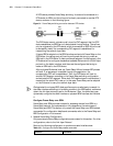
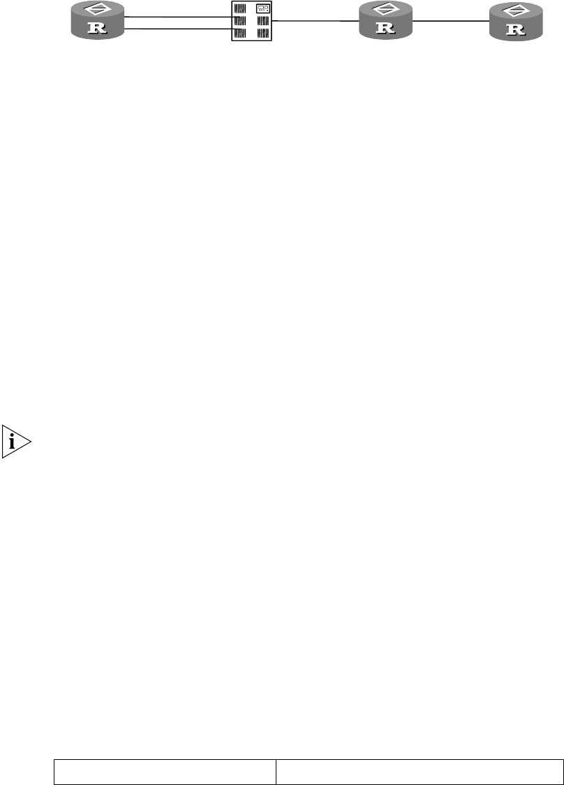
A DCE device provides Frame Relay switching. Its one end is connected to a
DTE device via ISDN, and the other end is directly connected to another DTE
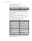
device, as shown in the following figure:
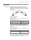
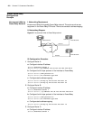
Figure 91 Frame Relay switching connection between DTE devices
The DCE device cannot originate a call, since the PVC segment that the DCE
device establishes via ISDN can only be activated through dialing. The call can
only be originated by the DTE device, which is connected to ISDN. After the call
is successfully made, the corresponding PVC segment is established for
transmitting the network layer data.
If legacy BDR is adopted on the ISDN interface worked with Frame Relay on the
DCE device, the calling party will use the configured dial string to make an
ISDN call to the DCE device. If dialer profiles are adopted, the calling party (the
DTE device) will re-configure the selected available B channel with the link layer
protocol on the dialer interface, and then use the configured dial string to
make an ISDN call to the DCE device.
After a physical B channel is set up, Frame Relay LMI and inverse ARP process
will start. If an agreement is reached through the negotiation, the
corresponding PVC will be established. Then, the DCE device will look for
another PVC segment according to the Frame Relay switching configuration
and activate the PVC segment. When both PVC segments are in active status, it
means that the whole PVC is set up. In this case, Frame Relay can be adopted
on the B channel to carry the network layer data.
Distinguished from legacy BDR, dialer profiles require a called party to search for
the dialer interface according to the dialing number in the ISDN packet, and hence
obtain the link layer protocol type for the B channel. Then, the called party can
dynamically configure the dialer interface or physical ISDN interface and initialize
it.
Configure Frame Relay over ISDN
Frame Relay over ISDN provides a means for accessing devices from ISDN to a
Frame Relay network. Its implementation fully depends on the techniques of
Frame Relay and BDR. This section only covers the Frame Relay over ISDN-related
commands. For configuration details and commands, refer to the Frame Relay and
BDR Configuration in this manual.
1 Related Frame Relay Configuration
Only some simple Frame Relay configurations are covered in this section. For other
configurations, refer to the Link Layer Protocol.
Perform the following configuration in synchronous serial interface view.
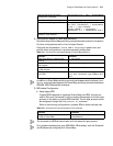
Table 313 Configure the Frame Relay-related commands
ISDN
Switch
Router A
DTE
DCE
Bri0
Bri1
Pri
DTE
Router C
S1
S1
Frame Relay
Switching
Router B
Operation Command