


Typical Frame Relay Configuration Example 281
II. Networking Diagram
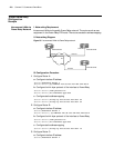
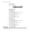
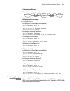
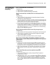
Figure 98 Networking diagram of Frame Relay over IP
III. Configuration Procedure
1 Configure RouterA
a Configure the Frame Relay interface Serial0
[Router]interface serial 0
[Router-Serial0]link-protocol fr
[Router-Serial0]fr interface-type dce
[Router-Serial0]fr dlci 100
b Configure IP interface Ethernet0
[Router]interface ethernet 0
[Router-Ethernet0]ip address 10.110.50.1 255.255.255.0
c Configure tunnel interface
[Router]interface tunnel 1
[Router-Tunnel1]source 10.110.50.1
[Router-Tunnel1]destination 10.110.50.2
d Configure Frame Relay over IP
[Router]interface serial 0
[Router-Serial0]fr dlci-switch 100 interface tunnel 1 dlci 200
2 Configure RouterB
a Configure the Frame Relay interface Serial0.
[Router]interface serial 0
[Router-Serial0]link-protocol fr
[Router-Serial0]fr interface-type dce
[Router-Serial0]fr dlci 300
b Configure IP interface Ethernet0
[Router]interface ethernet 0
[Router-Ethernet0]ip address 10.110.50.2 255.255.255.0
c Configure tunnel interface
[Router]interface tunnel 1
[Router-Tunnel1]source 10.110.50.2
[Router-Tunnel1]destination 10.110.50.1
d Configure Frame Relay over IP
[Router]interface serial 0
[Router-Serial0]fr dlci-switch 300 interface tunnel 1 dlci 200
Back-to-back Connection
through Frame Relay
over ISDN
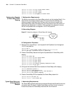
I. Networking Requirements
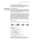
RouterA (DTE) and RouterB (DCE) are connected via ISDN. RouterA adopts legacy
BDR to make calls while RouterB adopts dialer profiles. To establish a PVC, the call
must be originated from RouterA.
Router A Router B
DLCI 300DLCI 100 DLCI 200 DLCI 200
E0 E0
IP Network
Tunnel
Frame Relay
Network
Frame Relay
Network