


236 CHAPTER 16: CONFIGURING LAPB AND X.25
[Router-Serial1]x25 x121-address 3333
[Router-Serial1]ip address 2.1.1.3 255.255.255.0
[Router-Serial1]x25 map ip 1.1.1.1 x121-address 1111
[Router-Serial1]x25 map ip 2.1.1.1 x121-address 1111
[Router-Serial1]x25 map ip 1.1.1.2 x121-address 2222
[Router-Serial1]x25 map ip 2.1.1.2 x121-address 2222
g Configure the static route to RouterA and RouterB.
[Router]ip route-static 10.1.1.0 24 1.1.1.1
[Router]ip route-static 10.1.1.0 24 2.1.1.1
[Router]ip route-static 10.2.1.0 24 1.1.1.2
[Router]ip route-static 10.2.1.0 24 2.1.1.2
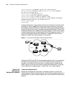
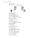
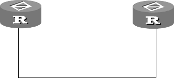
Interconnect LANs via
Annex G DLCIs
I. Networking Requirements
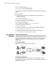
Two Routers are directly connected via serial interfaces. Router A works as Frame
Relay DCE whereas Router B as Frame Relay DTE.
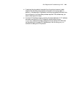
II. Networking Diagram
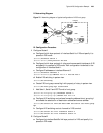
Figure 77 Interconnect LANs via an Annex G DLCI
III. Configuration Procedure
1 Configure RouterA:
a Create an X.25 template.
[Router]x25 template profile1
b Configure the local X.25 address.
[Router-x25-profile1]x25 x121-address 10094
c Map the destination X.25 address to the destination IP address.
[Router-x25-profile1]x25 map ip 202.38.163.252 x121-address 20094
[Router-x25-profile1]quit
d Configure an IP address for the local interface.
[Router]interface serial 1
[Router-Serial1]ip address 202.38.163.251 255.255.255.0
e Configure the link layer protocol of the interface to Frame Relay.
[Router-Serial1]link-protocol fr
[Router-Serial1]fr interface-type dce
f Configure a Frame Relay DLCI.
[Router-Serial1]fr dlci 100
g Configure the DLCI to be Annex G DLCI.
[Router-fr-dlci-100]annexg dce
h Associate the X.25 template with the DLCI.
IP:202.38.163.251 IP:202.38.163.252
DLCI=100
Router A
Router B