


Configure X.25 201
X.25 protocol can multiplex multiple virtual connection over a real physical link
between DTE and DCE, also called virtual circuit (VC) or logical channel (LC). X.25
can establish up to 4095 virtual connections numbered from 1 to 4095. The
number that can be employed to identify each virtual circuit (or logical channel) is
called logical channel identifier (LCI) or virtual circuit number (VCN).
Strictly speaking, virtual circuit and logical channel are two different concepts.
However, they are not much different at the user side.
X.25 protocol divides the logical channel into 4 areas. (listed here in numerically
increasing order): Permanent virtual circuits (PVCs), Incoming-only circuits,
Two-way circuits, Outgoing-only circuits.
According to the X.25 recommendation proposed by ITU-T, DCE selects an
available logical channel with a smaller number from the “one-way incoming call
channel range” and “two-way channel range” to initiate a call, while DCE selects
an available logical channel with a larger number from the “one-way incoming call
channel range” and “two-way channel range” to initiate a call. Thus, we can
avoid the case that one side of the communication occupies all the channels, and
minimize the possibility of call collision.
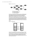
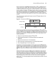
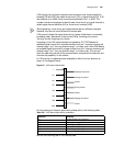
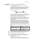
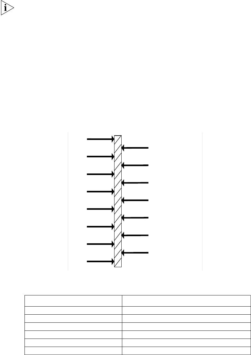
In X.25 protocol, six parameters are employed to delimit the four sections, as
shown in the diagram below.
Figure 62 X.25 channel delimitation
For the meanings of these six parameters, please refer to the following table.
Table 236 X.25 channel delimitation parameters
Perform the following task in the interface view:
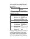
Parameter Meaning
LIC Lowest Incoming-only Channel
HIC Highest Incoming-only Channel
LTC Lowest Two-way Channel
HTC Highest Two-way Channel
LOC Lowest Outgoing-only Channel
HOC Highest Outgoing-only Channel
1
LTC
LIC
HTC
HIC
LOC
HOC
4095
Permanent virtual circuit
Incoming-only channel
Unused
Two-wa
y
channel
Unused
Outgoing-only channel
Unused