


VPDN and L2TP Overview 603
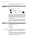
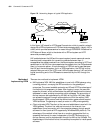
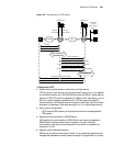
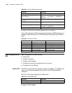
The networking diagram of these two typical methods is illustrated in the
following figure:
Figure 180 Networking diagram of two typical methods of VPDN
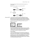
Overview of L2TP The L2TP (Layer 2 Tunneling Protocol) supports transmitting PPP frames by
tunneling, and the end of layer 2 data link and the PPP session can reside on
different devices, communicating based on packet switching which extends the
PPP model. Integrating the respective advantages of L2F protocol and PPTP, L2TP
has become the industrial standard of layer 2 tunneling protocol. The architecture
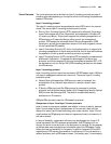
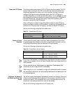
of the protocol stack to which the L2TP belongs is illustrated in
Figure 181.
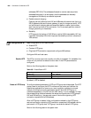
Figure 181 L2TP architecture
The L2TP architecture illustrated in Figure 181 describes the relation among PPP
frames, control channels and data channels. A PPP frame is first transmitted in the
unreliable data channel after being encapsulated with the L2TP header, and then
undergoes the packet transmission process of UDP, Frame Relay and ATM. A
control message is transmitted in the reliable L2TP control channel.
Tunnel and session
A L2TP tunnel is established between LAC and LNS, which is composed of one
control connection and n (n0) sessions. Only one L2TP tunnel can be established
between a pair of LAC and LNS. Both control message and PPP data message are
transmitted in the tunnel. A session is also established between LAC and LNS, but
session establishment must follow the successful establishment of the tunnel
(including the exchange of such information as identity protection, L2TP version,
frame type and hardware transmission type). One session connection corresponds
to one PPP data stream between LAC and LNS.
PSTN/ISDN
LAC
LNS
LAC
LNS
Internet
Internet
LAC Client
Remote
Client
HomeLAN
HomeLAN
Packet Transport (UDP,……)
L2TP Data Channel
(unreliable)
L2TP Data Messages
PPP Frames
L2TP Control Channel
(reliable)
L2TP Control Messages