


DCC Configuration Examples 745
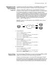
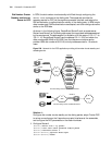
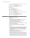
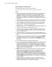
Figure 240 Network for the DCC application providing logic interface standby through
dialer route
Solution 1:
Adopt circular DCC and use the logic interface configured through the dialer
route command as the standby interface.
1 Configure RouterA:
[Router] dialer-rule 1 ip permit
[Router] interface serial 0
[Router-Serial0] physical-mode async
[Router-Serial0] modem
[Router-Serial0] ip address 100.1.1.1 255.255.255.0
[Router-Serial0] dialer enable-circular
[Router-Serial0] dialer-group 1
[Router-Serial0] dialer route ip 100.1.1.2 8810060 logic-channel 1
[Router-Serial0] interface serial 1
[Router-Serial1] ip address 200.1.1.1 255.255.255.0
[Router-Serial1] link-protocol ppp
[Router-Serial1] standby logic-channel 1
2 Configure RouterB:
[Router] dialer-rule 2 ip permit
[Router] interface serial 0
[Router-Serial0] physical-mode async
[Router-Serial0] modem
[Router-Serial0] ip address 100.1.1.2 255.255.255.0
[Router-Serial0] dialer enable-circular
[Router-Serial0] dialer-group 2
[Router-Serial0] dialer route ip 100.1.1.1 8810059 logic-channel 1
[Router-Serial0] interface serial 1
[Router-Serial1] ip address 200.1.1.2 255.255.255.0
[Router-Serial1] link-protocol ppp
[Router-Serial1] standby logic-channel 1
Solution 2:
Adopt circular DCC and use the logical interface configured through the dialer
route command as the main interface.
1 Configure RouterA:
[Router] dialer-rule 1 ip permit
[Router] interface serial 0
[Router-Serial0] physical-mode async
[Router-Serial0] modem
[Router-Serial0] ip address 100.1.1.1 255.255.255.0
[Router-Serial0] dialer enable-circular
[Router-Serial0] dialer-group 1
PSTN
8810060
Router A
Router B
ModemModem
Serial1
Serial0
Serial0
Serial1
8810059