


234 CHAPTER 16: CONFIGURING LAPB AND X.25
[Router]interface serial 0
[Router-Serial0]link-protocol x25 dte
[Router-Serial0]x25 x121-address 8888
The configurations of RouterC and RouterE are identical with the configuration of
RouterB
3 Configure RouterD
a Configure link layer protocol of interface Serial 0 to X.25 and specify it to
operate in DCE mode.
[Router]interface serial 0
[Router-Serial0]link-protocol x25 dce
b Configure IP addresses on interface Ethernet 0.
[Router]interface ethernet 0
[Router-Ethernet0]ip address 10.1.1.2 255.255.255.0
c Enable X.25 switching in system view.
[Router]x25 switching
d Configure X.25 switching route whose forwarding address is XOT Tunnel.
[Router]x25 switch svc 1111 xot 10.1.1.1
e Configure X.25 switching route that is forwarded to router RouterE
[Router]x25 switch svc 8888 interface serial 0
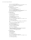
X.25 Load Balancing
Carrying IP Data
Transmission
I. Networking Requirements
X.25 packet switching networks interconnect IP networks in different areas and
X.25 networks carry IP data. At the same time, ISPs provide the function of X.25
network load balancing and implement the configuration of load balancing with
subscribers, to achieve the line load balancing when a server is accessed by
different clients.
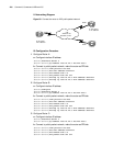
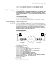
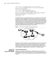
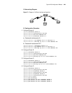
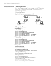
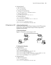
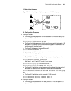
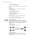
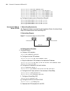
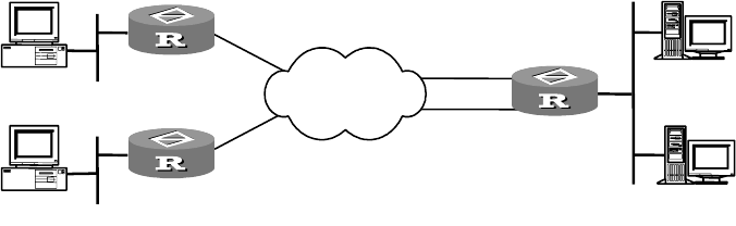
II. Networking Diagram
Figure 76 X.25 hunt group carrying IP data transmission
III. Configuration Procedure
In this example, ISP performs the configuration of load balancing on packet
switching exchange, therefore only the common X.25 configuration needs to be
implemented on routers.
PC B
10.2.1.2
QuidwayA
S0
1.1.1.3
S0
1.1.1.1
2.1.1.3
S1
S0
1.1.1.2
QuidwayC
Server A
10.3.1.2
Server B
10.3.1.3
PC A
10.1.1.2
X.25
packet
switching
network
E0
10.1.1.1
E0
10.2.1.1
E0
10.3.1.1
3333
1111
2222
QuidwayB