


Typical X.25 Configuration Example 239
[Router]x25 switch svc 1 interface serial 0
g Configure X.25 over Frame Relay switching.
[Router]x25 switch svc 2 interface serial 1 dlci 100
4 Configure the router Router C:
a Enable X.25 switching.
[Router]x25 switching
b Configure Serial 0 as the X.25 interface.
[Router]interface serial 0
[Router-Serial0]link-protocol x25 dce ietf
c Configure Serial 1 as the Frame Relay interface.
[Router]interface serial 1
[Router-Serial1]link-protocol fr
d Configure the Frame Relay Annex G DLCI.
[Router-Serial1]fr dlci 100
e Configure local X.25 switching.[Router-fr-dlci-100]annexg dte
[Router]x25 switch svc 2 interface serial 0
f Configure X.25 over Frame Relay switching.
[Router]x25 switch svc 1 interface serial 1 dlci 100
PVC Application of X.25
over Frame Relay
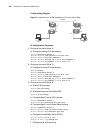
I. Networking Requirements
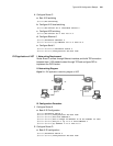
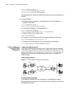
RouterA and RouterC are respectively connected to RouterB and RouterD through
X.25. RouterB and RouterC are connected through Frame Relay. Configure Frame
Relay Annex G DLCI 100 on both RouterB and RouterC to set up an X.25 PVC to
interconnect the two X.25 networks. Thereby, PC1 and PC2 can access each other.
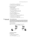
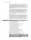
II. Networking Diagram
Figure 79 Networking for the PVC application of X.25 over Frame Relay
III. Configuration Procedure
1 Configure Router A:
a Configure the basic X.25 parameters.
[Router]interface serial 0
[Router-Serial0]switch svc x25 dte ietf
PC1
S0
S0
S0
S0
PC2
E0 E0
Router B
Router A
Router C
Router D
S1S1
DLCI100