


744 CHAPTER 51: CONFIGURING DCC
c Start dialing, and input the user name user1 and the password pass1.
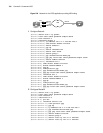
Solution 2:
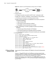
The dialing side uses a single number to dial, and the accessing side uses circular
DCC to set up the connection via the ISDN PRI interface. Configure the DCC
parameters on the dialer interface.
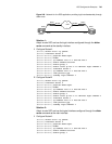
1 Configure RouterC:
[Router] dialer-rule 1 ip permit
[Router] local-user userb password simple passb
[Router] interface bri 0
[Router-Bri0] ip address ppp-negotiate
[Router-Bri0] dialer-group 1[Quidway-Bri0] dialer enable-circular
[Router-Bri0] dialer route ip 100.1.1.254 8810148
[Router-Bri0] link-protocol ppp
[Router-Bri0] ppp chap user user1
[Router-Bri0] ppp chap password simple pass1
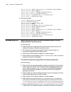
2 Configure RouterD:
[Router] dialer-rule 2 ip permit
[Router] local-user user1 password simple pass1
[Router] local-user user2 password simple pass2
……
[Router] local-user user16 password simple pass6
[Router] ip pool 1 100.1.1.1 100.1.1.16
[Router] controller e1 2
[Router-E1-2] pri-set
[Router-E1-2] interface serial 2:15
[Router-Serial2:15] ip address 100.1.1.254 255.255.255.0
[Router-Serial2:15] remote address pool 1
[Router-Serial2:15] dialer enable-circular
[Router-Serial2:15] dialer-group 2
[Router-Serial2:15] link-protocol ppp
[Router-Serial2:15] ppp authentication-mode chap
[Router-Serial2:15] ppp chap user userb
[Router-Serial2:15] ppp chap password simple passb
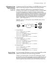
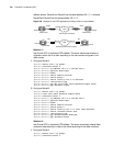
Logical Interface
Standby through Dialer
route for DCC
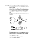
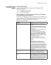
RouterA and RouterB are directly connected via the serial interfaces. At the same
time, RouterA forms a dialup connection with RouterB via a modem through
PSTN. RouterB cannot call RouterA via dialing.
As shown in Figure 240, a logical interface is generated through configuring the
dialer route command on RouterA. This interface can be used as either the
standby interface for other interfaces or the main interface. The port Serial0 on
RouterA is used as the dialer interface, and Serial1 is connected to RouterB
through straightforward DDN. The address of Serial0 on RouterA is 100.1.1.1, and
the address of the Serial1 connected to DDN is 200.1.1.1. The address of the
dialer interface on RouterB is 100.1.1.2, and the address of the interface
connected to DDN is 200.1.1.2.