Typical Configuration Example 193
Typical Configuration
Example
Interconnect Routers for
Data Transmission via
ISDN PRI Line
I. Networking Requirement
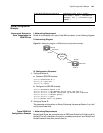
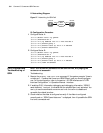
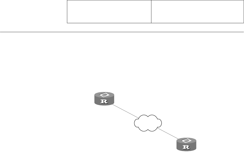
Router A is connected with router B via WAN, as shown in the following diagram.
II. Networking Diagram
Figure 56 Networking diagram of ISDN protocol configuration example
III. Configuration Procedure
1 Configure Router A:
a Create an ISDN PRI interface.
[Router]controller e1 0
[Router-E1-0]pri-set
[Router-E1-0]quit
b Configure the ISDN PRI interface.
[Router]interface serial 0:15
[Router-Serial0:15]ip address 202.38.154.1 255.255.0.0
[Router-Serial0:15]dialer route-info ip 202.38.154.2 8810154
[Router-Serial0:15]dialer-group 1
[Router-Serial0:15]quit
[Router]dialer-rule 1 ip permit
2 Configure Router B:
The parameter configuration on Router B is almost the same as Router A, so it will
not be mentioned here.
Typical ISDN DoV
Configuration Example
I. Networking Requirements
RouterA and Router are connected over an ISDN and RouterA will initiate a call to
RouterB. The call is handled in the way of processing a voice call, and RouterA and
RouterB transmit data after the call is set up.
Enable ISDN QSIG signaling debugging debugging isdn qsig { alarm |
call-state | error | information |
message | all } [ interface type
number ]
ISDN Exchange
202.38.154.1
202.38.154.2
8810152
8810154
Router A
Router B
cE1/PRI
cE1/PRI
Network


