OSPF Configuration Example 445
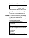
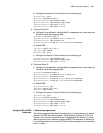
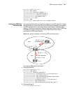
[RouterC] router id 3.3.3.3
[RouterC] ospf enable
[RouterC-ospf] interface ethernet 0
[RouterC-Ethernet0] ospf enable area 2
[RouterC-Ethernet0] interface serial 0
[RouterC-Serial0] ospf enable area 1
[RouterC-Serial0] quit
[RouterC] ospf
[RouterC-ospf] vlink peer-id 2.2.2.2 transit-area 1
Configuring OSPF Peer
Authentication
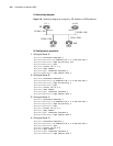
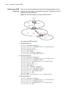
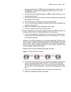
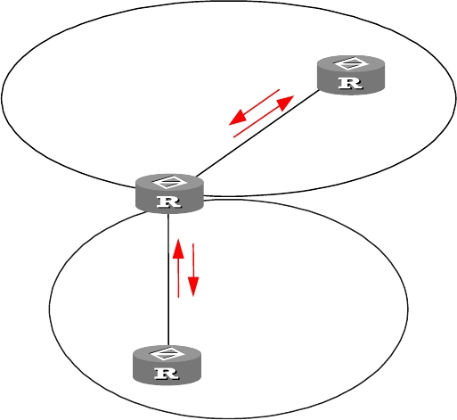
Verify peer authentication with simple text algorithm and MD5 algorithm. Simple
text authentication is used when Router A and Router B exchange route updating
and MD5 authentication is used when Router A and Router C exchange route
updating. The Ethernet interface of Router A and that of Router B are in OSPF area
0.The serial interface of Router A and that of Router B are both in area 1,
configured with MD5 authentication.
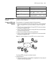
Figure 150 Networking diagram of configuring OSPF peer authentication
To configure OSPF peer authentication:
1 Configure Router A:
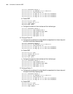
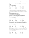
[RouterA] router id 1.1.1.1
[RouterA] ospf enable
[RouterA-ospf] interface ethernet 0
[RouterA-Ethernet0] ip address 192.1.1.1 255.255.255.0
[RouterA-Ethernet0] ospf enable area 0
[RouterA-Ethernet0] ospf authentication-mode simple 3Com
[RouterA-Ethernet0] interface serial 0
[RouterA-Serial0] ip address 193.1.1.1 255.255.255.0
[RouterA-Serial0] ospf enable area 1
[RouterA-Serial0] ospf authentication-mode md5 3Com 11
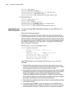
2 Configure Router B:
[RouterB] router id 2.2.2.2
Area 0
Area 1
E0 192. 1. 1. 2/ 24
S0 193. 1. 1. 1/ 24
MD5 authentication
Simple authentication
0
0
00
2.2.2.2
1.1.1.1
3.3.3.3
Router A
Router B
Router C
E0 192. 1. 1. 1/ 24
S0 193.1.1.2/24


