DCC Configuration Examples 731
DCC Configuration
Examples
DCC Applications in
Common Use
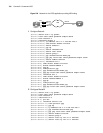
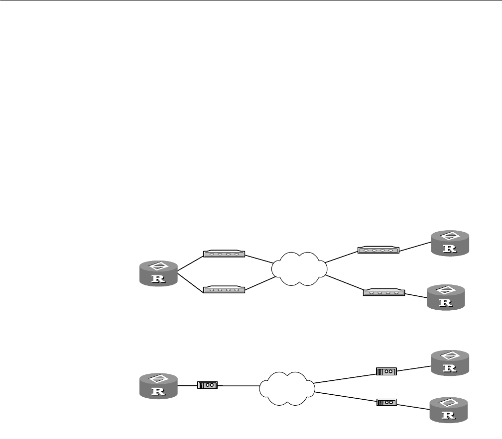
RouterA can call RouterB and RouterC via multiple interfaces. Likewise, RouterB
and RouterC can respectively call RouterA. However, RouterB and RouterC cannot
call each other.
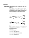
As shown in Figure 233, when circular DCC is used, the addresses of RouterA,
RouterB and RouterC are on the same segment. In this case, 100.1.1.1, 100.1.1.2,
and 100.1.1.3 are the addresses respectively for RouterA, RouterB and RouterC.
When resource-shared DCC are used, the addresses of RouterA and RouterB are
on the same segment, so are the addresses of RouterA and RouterC. The
addresses of the interfaces Dialer0 and Dialer1 on RouterA are respectively
100.1.1.1 and 122.1.1.1. The address of the Dialer0 on RouterB is 100.1.1.2, and
that of the Dialer0 on RouterC is 122.1.1.2.
Figure 233 Network of a DCC application in common use
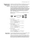
Solution 1
Establish a connection via the serial interface by using Circular DCC, configure the
DCC parameters on the dialer interface for RouterA with the help of a dialer
circular group, and directly configure the DCC parameters on the physical
interfaces on RouterB and RouterC.
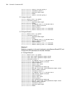
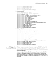
1 Configure RouterA:
[Router] dialer-rule 1 ip permit
[Router] interface dialer 0
[Router-Dialer0] ip address 100.1.1.1 255.255.255.0
[Router-Dialer0] dialer enable-circular
[Router-Dialer0] dialer-group 1
[Router-Dialer0] dialer route ip 100.1.1.2 8810052
[Router-Dialer0] dialer route ip 100.1.1.3 8810063
[Router-Dialer0] interface serial 0
[Router-Serial0] physical-mode async
[Router-Serial0] modem
Router A
Router C
Modem
Modem
Modem
PSTN
Modem
ISDN
8810048
8810049
8810052
8810063
Connecting via serial interfaces across PSTN
8810148
8810152
8810163
Connecting via ISDN BRI or PRI interfaces across ISDN
Router D
Router B
Router E
Router F
Serial0
Serial1
Serial0
Serial0
Bri0
Bri0
Bri0
NT1
NT1
NT1


