


406 CHAPTER 26: IP ROUTING PROTOCOL
of the router should be used to transfer a data packet to a sub-network or a host,
so the packet can reach the next router on this path, or reach the host as a directly
connected destination without passing through other routers.
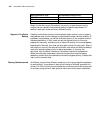
The routing table consists of the following key items:
■ Destination address: Identifies the destination address or destination
network of IP packets.
■ Network mask: Identifies, together with the destination address, the address
of the route segment where the destination host or router is located. For
example, if the destination address is 129.102.8.10 and the network mask is
255.255.0.0, the address of the route segment for the destination host or
router is 129.102.0.0. The mask consists of several consecutive 1s and 0s,
which can be expressed with dotted decimal system or with the number of
consecutive 1s in the mask.
■ Output interface: Indicates the interface of the router that forwards the IP
packet.
■ Next hop IP address: Indicates the next router to which the IP packet will be
forwarded.
■ The priority of this route added to IP routing table: Determines the best
route. There may be different next hops to the same destination. These routes
can be found by different routing protocols or they may be static routes
configured manually. The route with higher priority (smaller value) is the best
route. The user can configure multiple routes with different priorities to the
same destination and select one to forward messages.
According to the destination of a route, it can be classified as:
■ Sub-network route: The route whose destination is a sub-network
■ Host route: The route whose destination is a host
According to the connection mode between the destination and the router, you
can classify the router as:
■ Direct route: The destination address and the router are located in the same
segment.
■ Indirect route: The destination address and the router are not located in the
same segment.
To keep the routing table within a certain size, a default route is set. Whenever a
data packet fails to find the routing table, the default route is selected to transfer
the data packet.
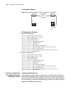
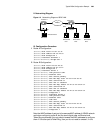
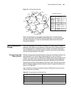
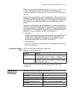
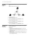
In complicated networks, the digits assigned to a router in each network are its
network address. For example, if router 8 (R8) is connected to three networks, it
has 3 IP addresses and 3 physical ports. The routing table is shown in the figure
below.