Typical X.25 Configuration Example 227
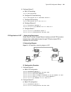
[Router-Serial0]x25 map ip 168.173.24.1 x121-address 30561001
[Router-Serial0]x25 map ip 168.173.24.2 x121-address 30561002
Configure Virtual Circuit
Range
I. Networking Requirement
The link layer protocol of router's interface Serial0 is X.25l, with the virtual circuit
range: permanent virtual circuit section [1, 8], incoming-only channel section [9,
16], two-way channel section [17, 1024], and the outgoing-only channel section is
disabled.
II. Configuration Procedure
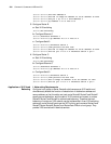
[Router]interface serial 0
[Router-Serial0]link-protocol x25
[Router-Serial0]x25 vc-range in-channel 9 16 bi-channel 17 1024
Transmit IP Datagram
via X.25 PVC
I. Networking Requirement
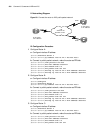
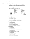
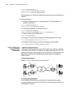
In the following diagram, the permanent virtual circuit section allowed by the
packet network is [1,8], the PVC numbers assigned to Router A and Router B are 3
and 4 respectively. The IP network addresses of Ethernet A and B are 202.38.165.0
and 196.25.231.0 respectively. It is required to exchange routing information
between Ethernet A and B with RIP routing protocol, so that PC A and PC B can
exchange information without adding static route.
II. Networking Diagram
Figure 70 X.25 PVC bearing IP data packet
III. Configuration Procedure
1 Configure Router A:
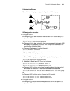
[Router]interface ethernet 0
[Router-Ethernet0]ip address 202.38.165.1 255.255.255.0
[Router-Ethernet0]interface serial 0
[Router-Serial0]ip address 192.149.13.1 255.255.255.0
[Router-Serial0]link-protocol x25
[Router-Serial0]x25 x121-address 1004358901
[Router-Serial0]x25 vc-range bi-channel 9 1024
[Router-Serial0]x25 pvc 3 ip 192.149.13.2 x121-address 1004358902
broadcast packet-size 512 512 window-size 5 5
[Router-Serial0]quit
[Router]rip
2 Configure Router B:
[Router]interface ethernet 0
X.25
windowsize: 5 5
packetsize: 512 512
RouterA
RouterB
IP: 192.149.13.1
X.121: 1004358901
IP: 192.149.13.2
X.121: 1004358902
PVC 3 PVC 4
EtherNet A
EtherNet B
PC BPC A
Serial 0 Serial 0


