


578 CHAPTER 40: CONFIGURING IPSEC
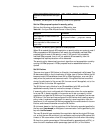
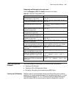
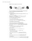
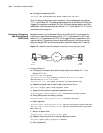
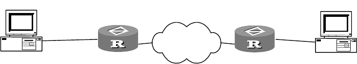
Figure 174 Networking diagram of manually creating SA
Prior to the configuration, you should ensure that Router A and Router B can
interwork at the network layer through a serial interface.
1 Configure Router A:
a Configure an access list and define the data stream from Subnet 10.1.1x to
Subnet 10.1.2x.
[RouterA] acl 101 permit
[RouterA-acl-101] rule permit ip source 10.1.1.0 0.0.0.255
destination 10.1.2.0 0.0.0.255
[RouterA-acl-101] rule deny ip source any destination any
b Create the IPSec proposal view named tran1
[RouterA] ipsec proposal tran1
c Adopt tunnel mode as the message-encapsulating form
[RouterA-ipsec-proposal-tran1] encapsulation-mode tunnel
d Adopt ESP protocol as security protocol
[RouterA-ipsec-proposal-tran1] transform esp-new
e Select authentication algorithm and encryption algorithm
[RouterA-ipsec-proposal-tran1] esp-new encryption-algorithm des
[RouterA-ipsec-proposal-tran1] esp-new authentication-algorithm
sha1-hmac-96
f Create a security policy with negotiation view as manual
[RouterA] ipsec policy policy1 10 manual
g Quote access list
[RouterA-ipsec-policy-policy1-10] security acl 101
h Quote IPSec proposal
[RouterA-ipsec-policy-policy1-10] proposal tran1
i Set local and remote addresses
[RouterA-ipsec-policy-policy1-10] tunnel local 202.38.163.1
[RouterA-ipsec-policy-policy1-10] tunnel remote 202.38.162.1
j Set SPI
[RouterA-ipsec-policy-policy1-10] sa outbound esp spi 12345
[RouterA-ipsec-policy-policy1-10] sa inbound esp spi 54321
k Set session key
[RouterA-ipsec-policy-policy1-10] sa outbound esp string-key abcdefg
[RouterA-ipsec-policy-policy1-10] sa inbound esp string-key gfedcba
PC A PC B
Internet
10.1.1.2
10.1.1.1
s0:202.38.163.1
s0:202.38.162.1
10.1.2.2
10.1.2.1
Router A Router B