


Sub-Interface 159
■ IPX network number which is different from that of the affiliated WAN
interface, and other IPX working parameters
■ Virtual circuit of the sub-interface
Please see chapters in Operation Manual - Link Layer Protocol and Operation
Manual - Network Protocol for details about the above configurations.
Configure sub-interfaces of WAN interface which link layer protocol is X.25
1 Create and delete WAN sub-interfaces
The command is the same as above.
2 Configure relevant working parameters
The following items can be configured on the sub-interface of WAN interface
which link layer protocol is X.25:
■ X.25 address mapping different from the affiliated WAN interface (i.e. the main
interface)
■ IP address which is not in the same network segment as the affiliated WAN
interface
■ IPX network number which is different from that of the affiliated WAN
interface, and other IPX working parameters
■ Virtual circuit of the sub-interface
Please see chapters in the Operation Manual - Link Layer Protocol and Operation
Manual - Network Protocol for details about the above configurations, and
sub-interface monitoring and maintenance. No further details are provided here.
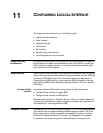
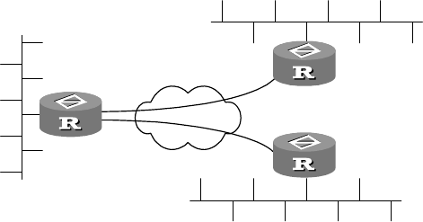
Typical WAN sub-interface configuration example
I. Networking Requirements
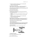
As shown below, WAN interface Serial0 of router A is connected with router B and
router C via public frame relay network. By configuring sub-interfaces on Serial0
of router A, LAN 1 can simultaneously access LAN 2 and LAN 3 via Serial0.
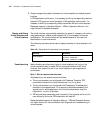
II. Networking Diagram
Figure 48 Networking diagram of WAN sub-interface configuration example
III. Configuration Procedure
1 Enter the view of WAN interface Serial0 of router A
[Router]interface serial 0
2 Select frame relay link layer protocol
Router A
Router B
Router C
Frame relay
Ethernet 1
Serial0
DLCI=50
202.38.160.1
202.38.161.2
129.9.0.0
Ethernet 3
Ethernet 2
DLCI=60
DLCI=70
DLCI=80
202.38.160.2
202.38.161.1
129.10.0.0
129.11.0.0