284 CHAPTER 17: CONFIGURING FRAME RELAY
2 Configure RouterB
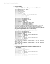
a Configure the BDR and Frame Relay parameters on the PRI interface.
[Router]dialer-rule 1 ip permit
[Router]fr switching
[Router]controller e1 0
[Router-E1-0]pri-set
[Router]interface dialer 0
[Router-Dialer0]ip address 110.0.0.2 255.255.255.0
[Router-Dialer0]dialer bundle 10
[Router-Dialer0]dialer-group 1
[Router-Dialer0]dialer number 660218
[Router-Dialer0]dialer call-in 660218
[Router-Dialer0]link-protocol fr
[Router-Dialer0]fr interface-type dce
[Router-Dialer0]fr dlci 100
[Router]interface serial 2:15
[Router-Serial2:15]undo dialer enable-legacy
[Router-Serial2:15]dialer bundle-member 10
[Router-Serial2:15]dialer bundle-member 20
For configuring the BDR and Frame Relay parameters on Dialer1, refer to the
configuration on Dialer0. The user only needs to change the IP address to
120.0.0.2, DLCI number to 200, and configure to receive the incoming calls from
the number 660208 and assign Dialer1 to Dialer Bundle 20.
b Configure the Frame Relay switching parameters on Serial1.
[Router-Serial1]link-protocol fr
[Router-Serial1]fr interface-type dce
[Router]interface serial 1.1
[Router-Serial1.1]ip address 130.0.0.1 255.255.255.0
[Router-Serial1.1]fr dlci 300
[Router]interface serial 1.2
[Router-Serial1.2]ip address 140.0.0.1 255.255.255.0
[Router-Serial1.2]fr dlci 400
c Configure Frame Relay SVCs.
[Router]fr switch myconnect1 interface dialer 0 dlci 100 interface
serial 1 dlci 300
[Router]fr switch myconnect2 interface dialer 1 dlci 200 interface
serial 1 dlci 400
3 Configure RouterC
a Configure IP addresses and DLCI numbers for the serial interface and
sub-interfaces.
[Router]interface serial 1
[Router-Serial1] link-protocol fr
[Router]interface serial 1.1
[Router-Serial1.1]ip address 130.0.0.2 255.255.255.0
[Router-Serial1.1]fr dlci 300
[Router]interface serial 1.2
[Router-Serial1.2]ip address 140.0.0.2 255.255.255.0
[Router-Serial1.2]fr dlci 400


