


398 CHAPTER 25: CONFIGURING DLSW
II. Networking Diagram
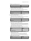
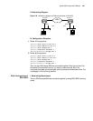
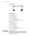
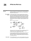
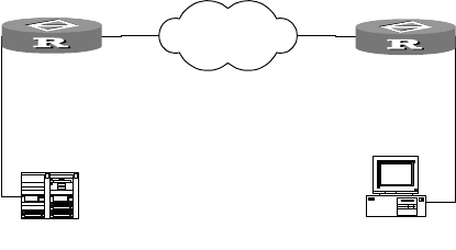
Figure 140 Networking diagram of DLSw configuration of SDLC-SDLC
III. Configuration Procedure
1 Router A Configuration:
[Router] dlsw local 110.87.33.11
[Router] dlsw remote 202.39.28.33
[Router] dlsw bridge-set 1
[Router] interface serial 0
[Router-Serial0] link-protocol sdlc
[Router-Serial0] baudrate 9600
[Router-Serial0] code nrzi
[Router-Serial0] sdlc status secondary
[Router-Serial0] sdlc mac-map local 00-00-11-11-00-00
[Router-Serial0] sdlc controller c1
[Router-Serial0] sdlc mac-map remote 00-00-22-22-00-c1 c1
[Router-Serial0] bridge-set 1
2 Router B Configuration:
[Router] dlsw local 202.39.28.33
[Router] dlsw remote 110.87.33.11
[Router] dlsw bridge-set 1
[Router] interface serial 1
[Router-Serial1] link-protocol sdlc
[Router-Serial1] baudrate 9600
[Router-Serial1] code nrzi
[Router-Serial1] sdlc status primary
[Router-Serial1] sdlc mac-map local 00-00-22-22-00-00
[Router-Serial1] sdlc controller c1
[Router-Serial1] sdlc mac-map remote 00-00-11-11-00-c1 c1
[Router-Serial1] bridge-set 1
Transform Configuration
from SDLC-LAN Remote
End Media to DLSw
I. Networking Requirement
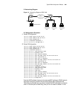
This example is a typical transform configuration from SDLC-LAN to DLSw and
SDLC includes multipoint support function. Among this, the connected node C1
and C2 are nodes of PU2.0 type (ATM) and C3 is node of PU2.1 type (OS2). The
port connected to multiplexer uses NRZ encoding mode and the port connected
separately uses NRZI encoding mode.
Router A
SDLC
IBM AS/400
PC(SNA)
SDLC address
0xC1
WAN(IP)
Router B
SDLC
110.87.33.11 202.39.28.33