


Access Navigator - Release 1.8 August 2003 6-11
Electrical Installation
Connect DSX-1 Cables to Access Navigator
Connect DSX-1 Cables to Access Navigator
CAUTION! SHIELDED DSX-1 CABLES WITH FERRITE BEAD RF SUPPRESSORS ARE
REQUIRED FOR COMPLIANCE WITH NEBS 1089 EMI/EMC AND FCC REQUIREMENT
P
ART 15, TO PREVENT RADIO FREQUENCY INTERFERENCE WITH OTHER EQUIPMENT.
E
NSURE THAT SHIELD DRAIN GROUND LUG IS GROUNDED TO CHASSIS THROUGH DS1
CONNECTOR.
NOTE: Use only #4-40 × 3/8" locking screws provided in Accessory Kit.
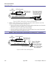
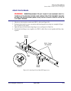
1. Refer to Figure 6-5.
2. Remove locking screw, if any, from DS1 Receive (IN) connector (see Figure 6-5).
3. Plug receive DSX-1 cable into DS1 Receive (IN) connector and snap clamp over cable side of
connector.
4. Position spade lug of shield drain wire under connector locking screw (#4-40 × 3/8") and tighten
with screw driver.
5. Verify that spade lug is firmly secured.
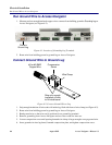
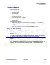
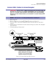
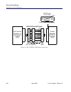
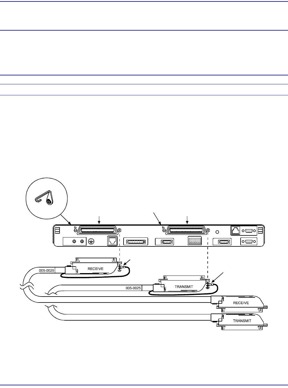
Figure 6-5. Location of Rear Panel DS1 Connectors
Insert shield drain
ground lug under
connector screw.
DS1 Transmit (OUT)
Connector
DS1 Receive (IN)
Connector
Connect the DSX-1 transmit and
receive cable plug ends with the
shield lug wires to the Access
Navigator. Note that both DSX-1
cables are identical (PN 005-0025).
Clamp
Clamp
Ground lug
DS1
Receive
IN
DS1
Transmit
OUT
Ti mi ng
In
Alarm Out
-48V
B
-48V
A
Alarm
In
Link OK
Ethernet
RS-232
CLI