


Access Navigator - Release 1.8 August 2003 6-33
Electrical Installation
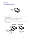
Wire Alarm Input Connector
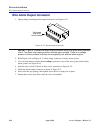
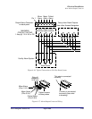
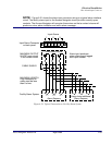
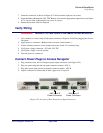
NOTE: Figure 6-21 shows the alarm input connector wiring to a typical alarm interface
circuit. The facility alarm input to the Access Navigator should provide normally open
contacts. The Access Navigator will energize these wires so that a contact closure will
produce a minor alarm indication and minor alarm message.
Figure 6-21. Typical Connections to Facility Alarm System
Input Alarms
Facility Alarm System
Input Alarm Connector
on back panel
MAXIMUM OUTPUT
24 VDC open circuit
10 mA closed circuit
Alarm Input Circuit
Alarm Sensors
123
MAXIMUM LENGTH
Loop resistance of
cable must be less
than 8 ohms
CABLE SHIELD
Daisy-chain additional
Alarm Sensors
Alarm input produces
minor alarm event tagged
with input number
123