


5-12 August 2003 Access Navigator - Release 1.8
Physical Installation
Install Crossbars
Install Crossbars
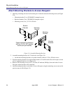
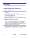
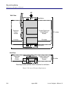
1. Position Vertical Mount Crossbars (refer to office records) so that inside mounting holes are 18.375
inches apart (see A in Figure 5-7 on page 5-13).
2. Attach crossbars to equipment rack with appropriate mounting screws (see B in Figure 5-7).
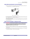
Attach Mounting Brackets to Access Navigator
NOTE: Universal rack mounting bracket kit includes hardware that is not required for
installation using crossbars.
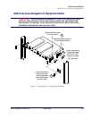
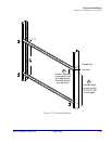
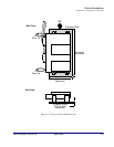
1. Open bag containing the universal rack mounting kit and select the following items (see A in Figure
5-8 on page 5-14):
• Mounting brackets (2 ea.), PN 0040303 (stamped on part)
• Mounting screws (4 ea.), 12-24 × 5/8inch, for attaching brackets to crossbars
2. Position mounting brackets for required flush mount or 5-inch forward offset with respect to front
rails of equipment rack (see B in Figure 5-8).
3. Remove four mounting screws (6-32 × 3/8 inch, 82º undercut, Phillips) from each side of Access
Navigator where brackets will be attached.
4. Attach mounting brackets to each side of Access Navigator using the mounting screws removed in
previous step (see C in Figure 5-8).
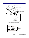
Attach Access Navigator to Crossbars
CAUTION! ACCESS NAVIGATOR REQUIRES AT LEAST 0.75 INCH OF FREE AIR
SPACE ON LEFT AND RIGHT SIDE OF CHASSIS FOR AIR CIRCULATION. INSUFFICIENT
SPACING MAY CAUSE SERVICE INTERRUPTIONS, RESULTING FROM EQUIPMENT
OVERHEATING AND SHUTTING DOWN. IF INSTALLING MORE THAN ONE ROW OF UNITS,
ENSURE THAT UNITS ARE MOUNTED DIRECTLY ABOVE OR BELOW UNITS IN OTHER ROWS
TO MAINTAIN UNOBSTRUCTED VERTICAL AIR CIRCULATION.
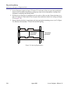
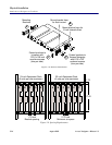
1. Position Access Navigator vertically in crossbar slot (refer to office records) with 1.75 inch
minimum bracket spacing (3 holes) between other brackets in row (see Figure 5-9 on page 5-14).
2. Secure mounting brackets to crossbar using 12-24 × 5/8inch mounting screws (see D in Figure 5-8
on page 5-14).