


5-16 August 2003 Access Navigator - Release 1.8
Physical Installation
Tools and Materials
Tools and Materials
Obtain the following tools and materials:
• Phillips screw drivers, #2 and #3
• Screws (8 ea.), #8 × 3/4 inch panhead
• Universal mounting kits (2 ea.), PN 710-0153.
(Access Navigator includes one kit.)
• Plywood, 3/4 inch thick, 10 × 21 inches minimum size
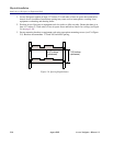
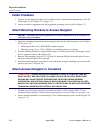
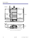
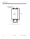
Ensure Adequate Clearance
Ensure there is adequate clearance around Access Navigator to access cards and connectors, and
sufficient space for proper ventilation (see Figure 5-10 on page 5-18).
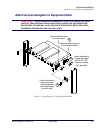
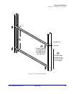
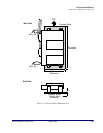
Prepare Plywood
1. Ensure that plywood is large enough to hold the Access Navigator (see Figure 5-11 on page 5-19).
Plywood should extend at least 1 inch beyond brackets.
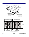
2. Mark mounting hole locations on plywood to ensure that brackets will mount squarely against
plywood (see Figure 5-12 on page 5-20).
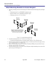
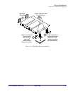
Attach Mounting Brackets to Access Navigator
NOTE: Universal mounting kit includes hardware that is not required for wall mount
installation.
1. Open bags containing the universal mounting kits and select the following items (see A in Figure
5-13 on page 5-21):
• Mounting brackets (4 ea.), PN 0040303 (stamped on part)
2. Position mounting brackets for wall mounting (see B in Figure 5-13).
3. Remove two mounting screws (6-32 × 3/8 inch, 82º undercut, Phillips) from Access Navigator
where each bracket will be attached (see C in Figure 5-13).
4. Attach mounting brackets to each side of Access Navigator using the mounting screws removed in
previous step (see C in Figure 5-13). Slide brackets down in screw slots to ensure maximum space
beneath Access Navigator for ventilation.