


6-36 August 2003 Access Navigator - Release 1.8
Electrical Installation
Wire Power Connectors
Wire Power Connectors
DANGER! HIGH VOLTAGE SHOCK HAZARD. DO NOT WIRE CONNECTORS WHILE
POWER IS ON.
CAUTION! BOTH POWER CONNECTORS MUST BE WIRED AND CONNECTED TO
POWER SOURCES. FAILURE TO DO SO WILL DISABLE REDUNDANT SWITCHING FEATURES
AND MAY INTERRUPT SERVICE.
WARNING! DO NOT APPLY POWER UNTIL TOLD TO DO SO. INCORRECT WIRING CAN
DAMAGE THE ACCESS NAVIGATOR OR THE POWER SOURCE.
NOTE: The Access Navigator has redundant internal power converters, one on each
Controller card. Two power input connectors are provided and both must be wired to a –
48V DC power source. It is recommended that each Controller card be powered
independently from separate power source. That way, if a Controller card or power source
fails, the redundant Controller card is capable of powering all circuits in the Access
Navigator. If separate –48V DC power sources are not available, then both power
connectors must be wired to the same power source.
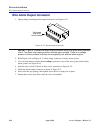
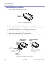
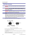
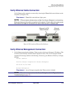
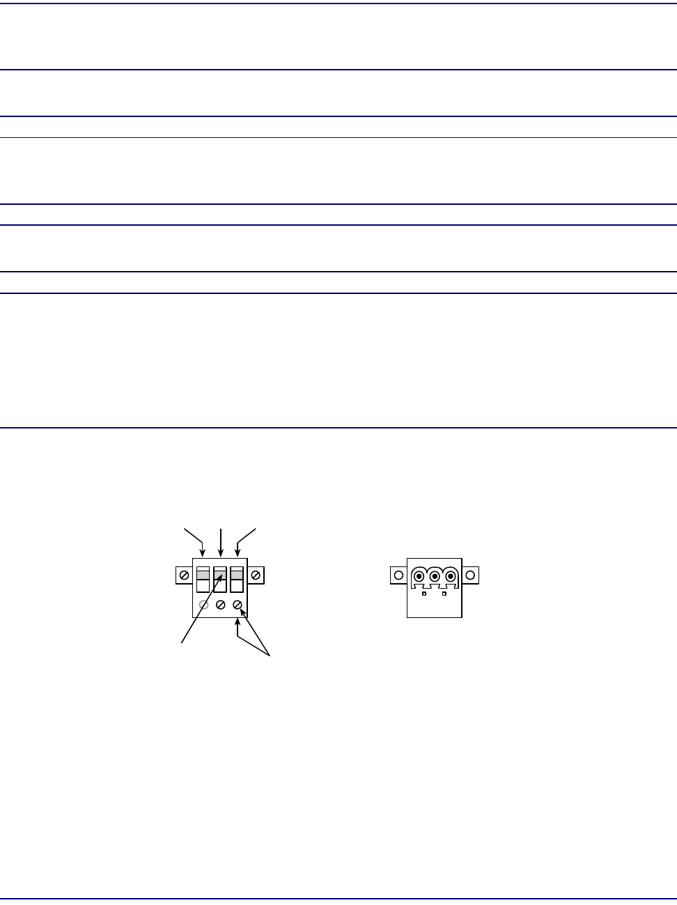
1. Open package containing 3-pin power connectors (2 ea.) (see Figure 6-23).
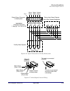
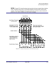
Figure 6-23. Power Connector Wiring
2. Wire each connector to a –48V DC power source providing –42V to –58V power.
3. Follow standard practice for power wiring.
4. 16 or 18 AWG insulated copper wire is recommended. (Connectors will accept 12 to 24 AWG solid
or stranded wire.)
5. Ensure that no power is present on the two wires to be connected. (Remove fuse or turn off circuit
breaker at power distribution panel.)
6. Strip the two wires from the power source so that 5/16 inch of bare wire is exposed.
Set screw may
be located on
front or bottom
Insert wire
in square hole
NOT
USED
-48 VDC
Battery
Battery
Return
Pin SideWire Side