


15-10 August 2003 Access Navigator - Release 1.8
Diagnostics & Troubleshooting
Indicator Descriptions
Indicator Descriptions
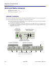
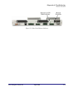
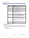
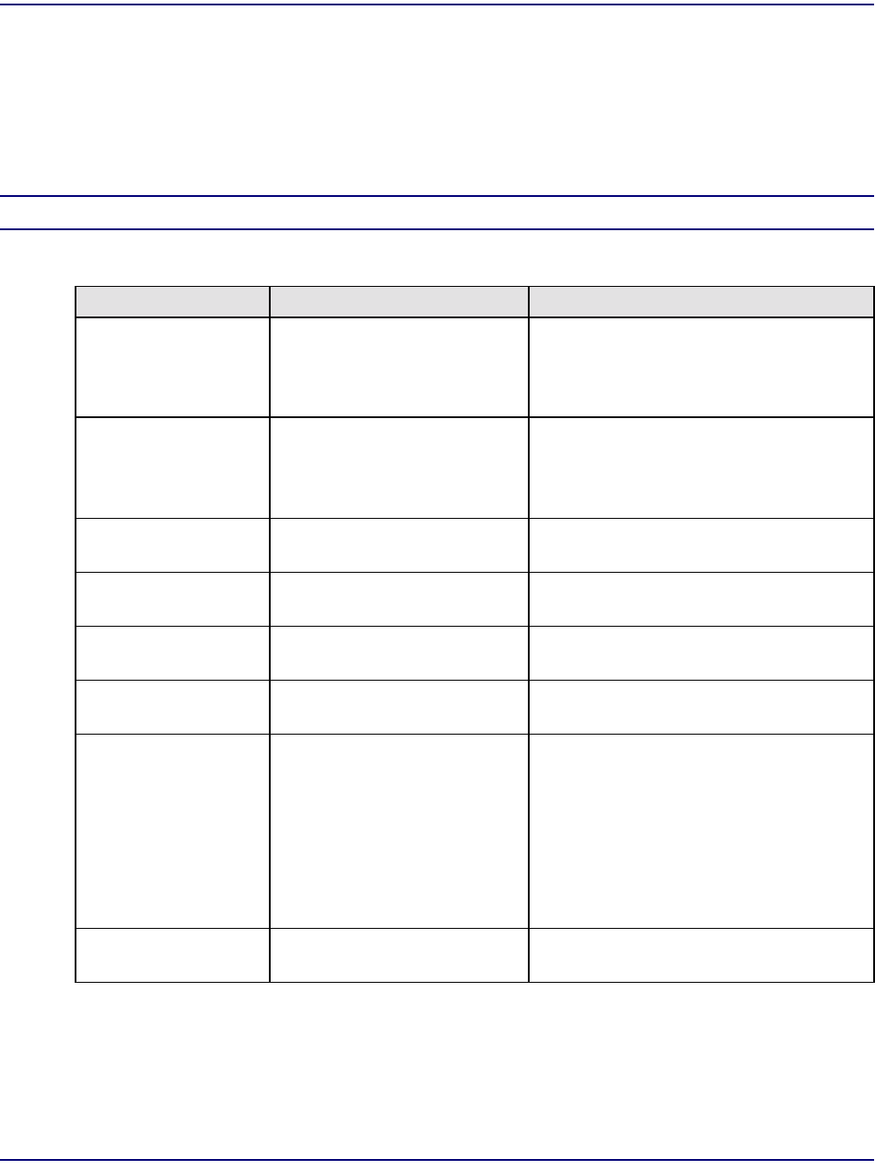
Each Controller card provides the following indicators (see Table 15-1). Only the active Controller card
will show alarm and status information. The LED on the active Controller will light green. On the
standby Controller, only the Power status indicator will light. The Power LED will light on the active
Controller.
NOTE: Note: Normal LED states are shown in Boldface type.
Table 15-1. Indicator Descriptions
LED State Description
Power
(Two LEDs, one for
each Controller card)
Off
Red
Yellow
Green
-48V power failure.
Internal power supply failure.
Card is booting up.
Normal operation.
Active (Controller) Off
Green
Yellow
Controller card is standby.
Controller card is active.
Insufficient memory. SIMM (memory
module) is required.
Critical Alarm Off
Red
No critical alarms present.
Critical alarm exists.
Major Alarm Off
Red
No major alarms present.
Major alarm exists.
Minor Alarm Off
Yellow
No minor alarms present.
Minor alarm exists.
ACO (alarm cut-off) Off
Yellow
Alarm(s) active.
Alarm(s) suppressed.
DS1 Status
(Each Quad T1
Framer card has four
LEDs)
Off
Red
Red Flashing Slow
Red Flashing Fast
Yellow
Yellow Flashing
Green
Green Flashing
Off-line.
Loss of signal (LOS).
Out of frame or AIS.
Self-test failure.
Line code violation (LCV).
Yellow alarm.
Normal operation.
Loopback test in progress.
Ethernet
(on rear panel)
Off
Green
No link or connection.
Normal operation.