


15-8 August 2003 Access Navigator - Release 1.8
Diagnostics & Troubleshooting
Alarm and Status Indicators
Alarm and Status Indicators
n Indicator Locations ... 15-8
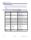
n Indicator Descriptions ... 15-10
Indicator Locations
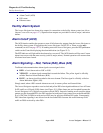
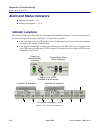
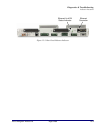
The Access Navigator provides LEDs for displaying status indications. Figure 15-2 shows the indicators on
the Access Navigator front panel, and Figure 15-3 shows the rear panel.
l Each Controller card (A and B) has its own set of indicators, but only the power status indicator
will light on the standby Controller card.
l Each Quad T1 Framer (QF) card has status indicators for four DS1s. The Access Navigator holds
up to 8 QF cards, providing up to 32 DS1 circuits. DS1 indicators will not light for DS1s that are
not installed or in service.
Figure 15-2. Front Panel Indicators
Controller ’A’ Indicators Controller ’B’ Indicators
Critical, Major, Minor
Alarm Indicators
Power and
Active/Standby
Indicators
Alarm Cutoff (ACO)
Pushbutton and Indicator
DS1 Status Indicators (1 to 32)