


Access Navigator - Release 1.8 August 2003 6-41
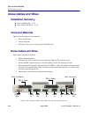
Electrical Installation
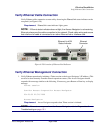
Verify Chassis Ground Connection
Verify Chassis Ground Connection
Follow standard practices to verify chassis ground connection to building ground system.
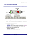
Verify DSX-1 Connections
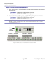
NOTE: Acceptance test requires temporary loopback between the DSX-1 transmit and
DSX-1 receive connectors, either by cross-connecting DS1s at the patch panel or by
plugging a DSX-1 cable from the transmit output to the receive input connectors. The
Access Navigator can be equipped with up to 32 DS1 interfaces.
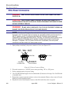
1. Establish temporary loopback or cross-connect between DS1 receive and transmit signals at the
DSX-1 interface or patch panel.
2. Turn on –48 VDC power, if not already on.
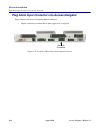
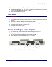
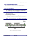
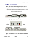
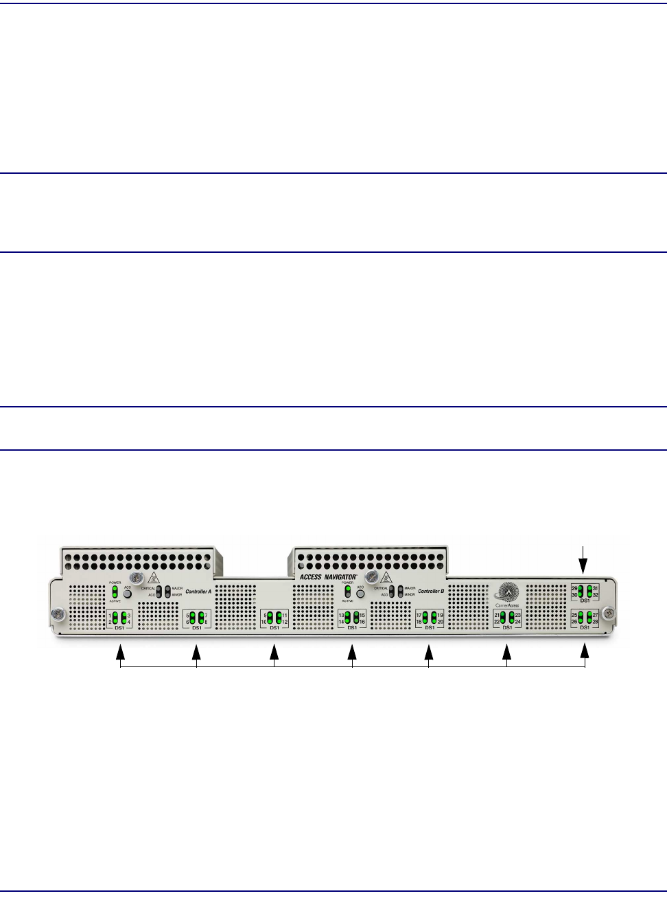
3. Verify the following front panel status indications (see Figure 6-27).
Requirement: DS1 status indicators light green for all installed circuit cards when DS1
transmit outputs are looped back to DS1 receive inputs.
NOTE: If status indications are incorrect, refer to Diagnostics & Troubleshooting on
page 15-1.
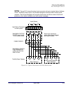
Figure 6-27. Location of Front DS1 Status Indicators
DS1 Status
Indicators
#29 to #32
DS1 Status
Indicators
#1 to #28