


Access Navigator - Release 1.8 August 2003 6-29
Electrical Installation
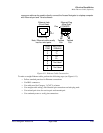
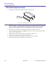
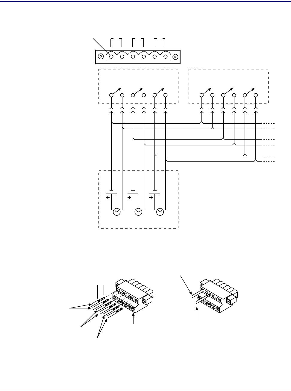
Wire Alarm Output Connector
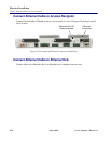
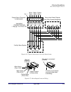
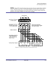
Figure 6-16. Typical Connections to Facility Alarm System
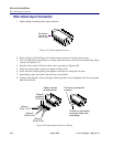
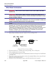
Figure 6-17. Alarm Output Connector Wiring
Pin 1
Critical
Alarm
Major
Alarm
Minor
Alarm
Facility Alarm System
Output Alarm Connector
on back panel
Alarm Panel
Normally open contacts
Alarm Output Circuit
MAXIMUM
CONTACT RATING
1 Amp @ 110 V AC or DC
Daisy-chain Alarm Outputs
from other Access Navigators
Minor Alarm
(Pins 1 & 2)
Major Alarm
(Pins 3 & 4)
Critical Alarm
(Pins 5 & 6)
Strip off
insulation
5/16 inch
This wire is connected
correctly
This wire is connected
incorrectly (bare wire
is showing)
Tighten screws
to clamp wires