


Access Navigator - Release 1.8 August 2003 6-37
Electrical Installation
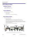
Verify Wiring
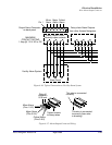
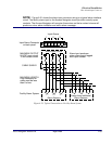
7. Orient the connector as shown in Figure 6-23 and loosen the right two set screws.
8. Insert the Battery Return and –48V VDC Battery wires into the appropriate square holes (see Figure
6-23), one at a time, tightening the set screws as you go.
9. Ensure that no bare wires are exposed.
Verify Wiring
WARNING! INCORRECT VOLTAGE POLARITY CAN DAMAGE ACCESS NAVIGATOR.
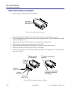
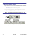
1. Use voltmeter to verify wiring of both power connectors (Figure 6-24) before plugging into Access
Navigator.
2. Apply power to connector. (Replace fuse or turn on circuit breaker.)
3. Touch voltmeter probes to screw clamps below pins 2 and 3 of connector plug.
4. Verify that voltage is between –42V and –58V DC.
5. Verify that voltage is correct polarity.
6. Turn off power to connectors.
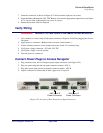
Connect Power Plugs to Access Navigator
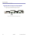
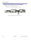
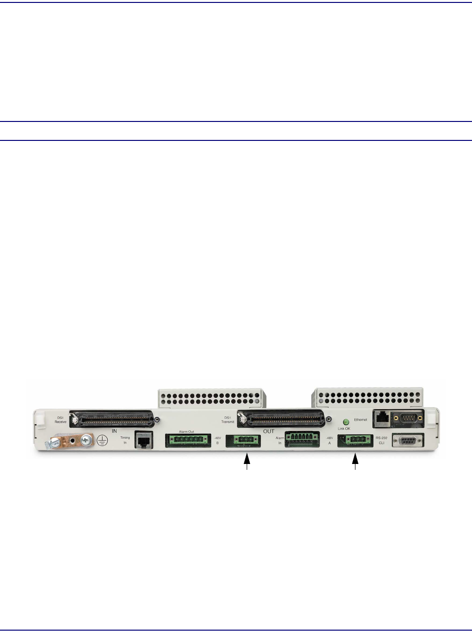
1. Plug connectors into Access Navigator power input connectors (see Figure 6-24).
2. Plug one power plug into the rear panel connector market –48V A.
3. Plug other power plug into the rear panel connector market –48V B.
4. Inspect connectors to ensure that no bare copper wire is exposed.
Figure 6-24. Location of Rear Panel Power Input Connectors
–48V Input ‘B’
Power Connector
–48V Input ‘A’
Power Connector