


3-40 Intel® PXA255 Processor Developer’s Manual
Clocks and Power Manager
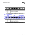
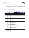
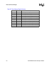
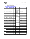
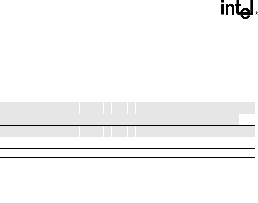
3.7.2 Power Mode Register (PWRMODE)
The PWRMODE register (CP14, register 7), shown in Table 3-25, is used to enter idle and sleep
modes. To select a mode, software writes to PWRMODE[M]. All core-initiated memory requests
are completed before the Clocks and Power Manager initiates the desired mode.
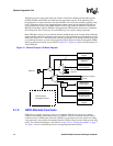
3.8 External Hardware Considerations
The Clocks and Power Manager controls the timing in and out of resets and the voltage ramp and
stabilization. As a result, the hardware that is used with the processor must meet certain
requirements to operate properly. This section describes those requirements.
3.8.1 Power-On-Reset Considerations
The nRESET and nTRST pins must be held low while the power supplies initialize and for a fixed
time after power is stable. This can be controlled with an external Power-On-Reset device or
another circuit.
To ensure that the internal ESD protection devices do not activate during power up, a minimum rise
time must be observed. Refer to the Intel® PXA255 Processor Electrical, Mechanical, and
Thermal Specification for details.
3.8.2 Power Supply Connectivity
The processor requires two or three externally-supplied voltage levels. VCCQ requires 3.3 V (+/-
10%), VCCN requires 3.3 V (+/- 10%) or 2.5 V (+15/-5%), and VCC and PLL_VCC shall be
connected together and require .85-1.3 V. PLL_VCC must be separated from other low voltage
supplies. Depending on the availability of independent regulator outputs and the desired memory
voltage, VCCQ may have to be separated from VCCN.
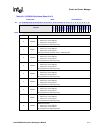
Table 3-25. PWRMODE Bit Definitions
CP14
Register 7
PWRMODE CP14
Bit
31 30 29 28 27 26 25 24 23 22 21 20 19 18 17 16 15 14 13 12 11 10 9 8 7 6 5 4 3 2 1 0
reserved M
Reset
0 0 0 0 0 0 0 0 0 0 0 0 0 0 0 0 0 0 0 0 0 0 0 0 0 0 0 0 0 0 0 0
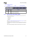
Bits Name Description
[31:2] — reserved
[1:0] M
Low Power Mode
00 – Run/turbo mode
01 – Idle mode
10 – reserved
11 – Sleep mode
Set to 00 on reset.