Intel® PXA255 Processor Developer’s Manual 4-41
System Integration Unit
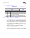
4.5.2.2 PWM Duty Cycle Registers (PWM_DUTYn)
The PWM_DUTYn, shown in Table 4-47, contains two fields:
• FDCYCLE
• DCYCLE
The FDCYCLE bit determines whether or not PWM_OUTn is a function of the DCYCLE bits in
the PWM_DUTYn register or is set high. When the FDCYCLE bit is cleared low (normal
operation), the output waveform of PWM_OUTn is cyclic, with PWM_OUTn being high for the
number of PSCLK_PWMn periods equal to DCYCLE.
If FDCYCLE=0x0 and DCYCLE=0x0, PWM_OUTn is set low and does not toggle.
Note: If FDCYCLE is 0b1, PWM_OUTn is high for the entire period and is not influenced by the value
programmed in the DCYCLE bits.
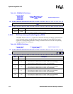
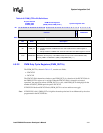
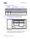
Table 4-46. PWM_CTRLn Bit Definitions
Physical Address
0x40B0_0000
0x40C0_0000
PWM Control Registers
(PWM_CTRL0, PWM_CTRL1)
System Integration Unit
Bit
31 30 29 28 27 26 25 24 23 22 21 20 19 18 17 16 15 14 13 12 11 10 9 8 7 6 5 4 3 2 1 0
reserved
PWM_SD
PRESCALE
Reset
0 0 0 0 0 0 0 0 0 0 0 0 0 0 0 0 0 0 0 0 0 0 0 0 0 0 0 0 0 0 0 0
Bits Name Description
<31:7> — reserved
<6> PWM_SD
PWMn Shutdown Method:
0 – Graceful shutdown of PWMn when the clock enable bit in the CKEN register is
cleared.
1 – Abrupt shutdown of PWMn when the clock enable bit in the CKEN register is cleared.
<5:0> PRESCALE
PWMn Prescale Divisor.
Determines the frequency of the PWM module clock (in terms of the 3.86 MHz clock)
PSCLK_PWMn = 3.6864 MHz / (PWM_CTRL[PRESCALE] + 1)


