Intel® PXA255 Processor Developer’s Manual 7-21
LCD Controller
status register (LCSR) is set, an interrupt request is made to the interrupt controller. When SFM=1,
the interrupt is masked and the state of the SOF status bit is ignored by the interrupt controller.
Setting SFM does not affect the current state of SOF or the LCD controller’s ability to set and clear
SOF, it only blocks the generation of the interrupt request.
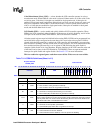
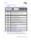
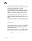
LCD Disable Done Interrupt Mask (LDM) — used to mask interrupt requests that are asserted
after the LCD is disabled and the frame currently being sent to the output pins has completed.
When LDM=0, the interrupt is not masked, and whenever the LCD disable done (LDD) status bit
in the LCD status register (LCSR) is set to one, an interrupt request is made to the interrupt
controller. When LDM=1, the interrupt is masked, and the state of the LDD status bit is ignored by
the interrupt controller. Setting LDM does not affect the current state of LDD or the LCD
controller’s ability to set and clear LDD, it only blocks the generation of the interrupt request. This
interrupt is used when the LCD must be disabled after the current frame being sent to the output
pins has completed. Clearing LCD Enable (ENB) is a quick disable, and LDD is not set.
Note: This mask bit applies only to regular shutdowns using the LCD Disable (DIS) bit.
Single-/Dual-Panel Select (SDS) — In passive mode (PAS=0), SDS is used to select the type of
display control implemented by the LCD screen. When SDS=0, single-panel operation is selected
(pixels presented to screen a line at a time). When SDS=1, dual-panel operation is selected (pixels
presented to screen two lines at a time). Single-panel LCD drivers have one line/row shifter and
driver for pixels and one line pointer. Dual-panel LCD controller drivers have two line/row shifters
(one for the top half of the screen, one for the bottom) and two line pointers (one for the top half of
the screen, one for the bottom).
When dual-panel mode is programmed, both of the LCD controller’s DMA channels are used.
DMA channel 0 is used to load the palette RAM from the frame buffer and to drive the upper half
of the display, and DMA channel 1 drives the lower half. The two channels alternate when fetching
data for both halves of the screen, placing encoded pixel values in the two separate input FIFOs.
When dual-panel operation is enabled, the LCD controller doubles its pin usage. For monochrome
screens, eight pins are used and for color screens, 16 pins are used.
Note: SDS must be set to 0 in active mode (PAS=1).
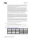
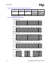
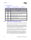
Table 7-3 shows the LCD data pins and GPIO pins used for each mode of operation and the
ordering of pixels delivered to a screen for each mode of operation.
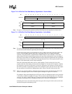
Note: In passive color mode, the data pin ordering switches. Figure 7-18 shows the LCD data pin pixel
ordering.
.
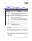
Table 7-2. LCD Controller Data Pin Utilization (Sheet 1 of 2)
Color/Monochrome
Panel
Single/
Dual Panel
Passive/
Active Panel
Screen Portion Pins
Monochrome Single Passive Whole L_DD[3:0]
Monochrome Single Passive Whole L_DD[7:0]
†
Monochrome Dual Passive
Top L_DD[3:0]
Bottom L_DD[7:4]
Color Single Passive Whole L_DD[7:0]


