Intel® PXA255 Processor Developer’s Manual 7-39
LCD Controller
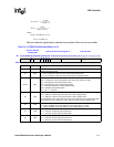
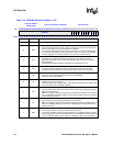
panels. When OU is set, an interrupt request is made to the interrupt controller if it is unmasked
(LCCR0[OUM] = 0). Output FIFO underruns are more important that Input FIFO underruns,
because they affect the panel.
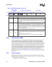
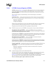
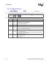
Input FIFO Underrun Upper Panel Status (IUU) — set when the upper panel’s input FIFO is
completely empty and the LCD controller’s pixel unpacking logic attempts to fetch data from the
FIFO. It is cleared by writing one to the bit. IUU is used in both single-panel (LCCR0[SDS] = 0)
and dual-panel (SDS = 1) modes. When IUU is set, an interrupt request is made to the interrupt
controller if it is unmasked (LCCR0[IUM] = 0).
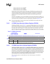
Input FIFO Underrun Lower Panel Status (IUL) — used only in dual-panel mode
(LCCR0[SDS] = 1) and is set when the lower panel’s input FIFO is completely empty and the LCD
controller’s pixel unpacking logic attempts to fetch data from the FIFO. It is cleared by writing one
to the bit. When IUL is set, an interrupt request is made to the interrupt controller if it is unmasked
(LCCR0[IUM]=0).
AC Bias Count Status (ABC) — set each time the AC bias pin (L_BIAS) toggles the number of
times specified in the AC bias pin transitions per interrupt (API) field in LCCR3. If API is
programmed with a non-zero value, a counter is loaded with the value in API and is decremented
each time L_BIAS toggles. When the counter reaches zero, ABC is set, which signals an interrupt
request to the interrupt controller. The counter reloads using the value in API but does not start to
decrement again until ABC is cleared by software.
Bus Error Status (BER) — set when a DMA transfer causes a system bus error. The error is
signalled when the DMA controller attempts to access a reserved or nonexistent memory space.
When this occurs, the DMA controller stops and remains halted until software installs a valid
memory address into the FDADRx register. In dual-channel mode, both channels are stopped.
FDADR0 and FDADR1 must be rewritten to continue LCD operation. BER remains set until
cleared by software.
Start Of Frame Status (SOF) — set after the DMA controller has loaded a new descriptor and
that descriptor has the start of frame interrupt bit set (LDCMDx[SOFINT] = 1). When SOF is set,
an interrupt request is made to the interrupt controller if it is unmasked (LCCR0[SFM] = 0). In
dual-panel mode (LCCR0[SDS] = 1), both DMA channels are enabled, and SOF is set only after
both channels’ descriptors have been loaded. SOF remains set until cleared by software.
LCD Disable Done Status (LDD) — set by hardware after the LCD has been disabled and the
frame that is active has been sent to the LCD data pins. When the LCD controller is disabled by
setting the LCD disable bit
in LCCR0, the current frame is completed before the controller is
disabled. After the last set of pixels is clocked out onto the LCD data pins by the pixel clock, the
LCD controller is disabled, LDD is set, and an interrupt request is made to the interrupt controller
if it is unmasked (LCCR0[LDM] = 0). LDD remains set until cleared by software.
Performing a quick disable by clearing LCCR0[ENB] does not set LDD.
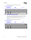
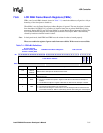
This is a read/write register. Ignore reads from reserved bits. Write zeros to reserved bits.


