3-2 Intel® PXA255 Processor Developer’s Manual
Clocks and Power Manager
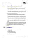
3.2 Power Manager Introduction
The Clocks and Power Manager can place the processor in one of three resets.
• Hardware Reset (nRESET asserted) is a nonmaskable total reset. It is used at power up or
when no system information requires preservation.
• Watchdog Reset is asserted through the Watchdog Timer and resets the system except the
Clocks and Power Manager. This reset is used as a code monitor. If code fails to complete a
specified sequence, the processor assumes a fatal system error has occurred and causes a
Watchdog Reset.
• GPIO Reset is enabled through the GPIO alternate function registers. It is used as an
alternative to Hardware Reset that preserves the Memory Controller registers and a few critical
states in the Clocks and Power Manager and the Real Time Clock (RTC).
The Clocks and Power Manager also controls the entry into and exit from any of the low power or
special clocking modes on processor. These modes are:
• Turbo Mode: the Core runs at its peak frequency. In this mode, make very few external
memory accesses because the Core must wait on the external memory.
• Run Mode: the Core runs at its normal frequency. In this mode, the Core is assumed to be
doing frequent external memory accesses, so running slower is optimum for the best power/
performance trade-off.
• Idle Mode: the Core is not being clocked, but the rest of the system is fully operational. This
mode is used during brief lulls in activity, when the external system must continue operation
but the Core is idle.
• Sleep Mode: places the processor in its lowest power state but maintains I/O state, RTC, and
the Clocks and Power Manager. Wake-up from Sleep Mode requires re-booting the system,
since most internal state was lost. The core power must be grounded in sleep to prevent current
leakage.
The Clocks and Power Manager also controls the processor’s actions during the Frequency Change
Sequence. The Frequency Change Sequence is a sequence that changes the Core Frequency (Run
and Turbo) and Memory Frequency from the previously stored values to the new values in the Core
Clock Configuration register. This sequence takes time to complete due to PLL relock time, but it
allows dynamic frequency changes without compromising external memory integrity. Any
peripherals that rely on the Core or Memory Controller must be configured to withstand a data flow
interruption.
3.3 Clock Manager
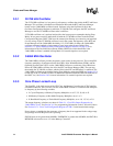
The processor’s clocking system incorporates five major clock sources:
• 32.768 kHz Oscillator
• 3.6864 MHz Oscillator
• Programmable Frequency Core PLL
• 95.85 MHz Fixed Frequency Peripheral PLL
• 147.46 MHz Fixed Frequency PLL


