Intel® PXA255 Processor Developer’s Manual 5-21
DMA Controller
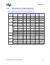
5.3.5 DMA Source Address Registers
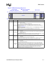
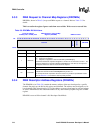
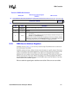
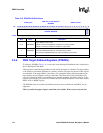
DSADRx, shown in Table 5-10, are read only in the Descriptor Fetch Mode and are read/write in
the No-Descriptor Fetch Mode.
DSADRx contains the Source Address for the current descriptor of a specific channel. The Source
Address is the address of the internal peripheral or a memory location. On power up, the bits in this
register are undefined. If the Source Address is the address of a companion chip or external
peripheral, the source address must be aligned to an 8-byte boundary. This allows bits [2:0] of the
address to be reserved. If the source address is the address for an internal peripheral, the address
must be 32-bit aligned, so bits [1:0] are reserved. DSADR cannot contain the address of any other
internal DMA, LCD, or MEMC registers.
This is a read/write register. Ignore reads from reserved bits. Write zeros to reserved bits.
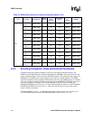
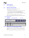
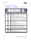
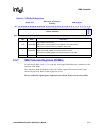
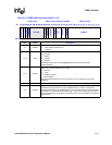
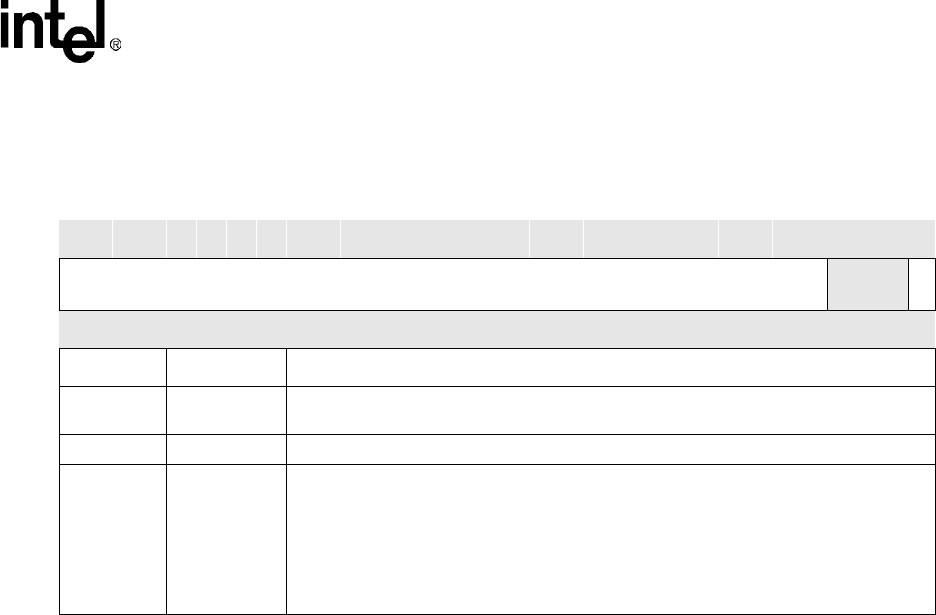
Table 5-9. DDADRx Bit Definitions
0x4000_02x0
DMA Descriptor Address Register
(DDADRx)
DMA Controller
Bit
31 30 29 28 27 26 25 24 23 22 21 20 19 18 17 16 15 14 13 12 11 10 9 8 7 6 5 4 3 2 1 0
DESCRIPTOR ADDRESS
reserved
STOP
Reset Uninitialized 0
Bits Name Description
31:4
DESCRIPTOR
ADDRESS
Address of next descriptor (read / write).
3:1 — reserved
0STOP
Stop (read / write).
0 – Run channel.
1 – Stop channel after completely processing this descriptor and before fetching the next
descriptor, i.e., DCMD[LENGTH]= 0.
If this bit is set, the channel to stops after it completely processes the descriptor and before
it fetches the next descriptor. If the DDADRx[STOP] bit is 0, a new descriptor fetch based
on the DDADR starts when the current descriptor is completely processed.


