7-14 Intel® PXA255 Processor Developer’s Manual
LCD Controller
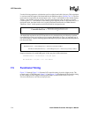
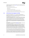
Use the following equation to calculate the total size of the frame buffer (in bytes). This calculation
is used to encode the length of the frame buffer in the DMA descriptors (Section 7.6.5.4). The first
term is the size required for the encoded pixel values. “Lines” is the number of lines for the display.
“Pixels” is the number of pixels per line. Use the actual line/pixel count, not minus 1 as in the
LCCR registers. “n” = the number of extra dummy pixels required per line, as described above. For
dual-panel mode, the frame buffer size is equally distributed between the two DMA channels.
Therefore, “Lines” in this equation are divided in half for dual-panel mode.
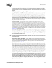
The bandwidth required for the LCD Controller can be calculated using the following equations.
FrameBufferSize is the result of the previous equation. Bandwidth is always an important part of
any system analysis. Systems with large panels and high bits per pixel must ensure that the panel is
not starved for data.
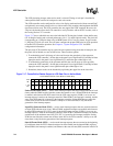
Sample calculations for an 640x480 panel, 16 bits per pixel, 60 Hz refresh rate:
FrameBufferSize = 16*640*480/8 = 614,400 bytes
Bus Bandwidth = 614,400 * 60 = 36.9 MB/sec
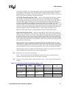
7.5 Functional Timing
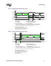
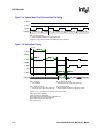
Figure 7-12 through Figure 7-14 illustrate LCD controller timing in passive display mode. The
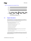
example used is a 320x240 panel. Figure 7-15 and Figure 7-16 illustrate the LCD controller timing
in active display mode.For precise timing relationships, see the Intel® PXA255 Processor
Electrical, Mechanical, and Thermal Specification.
FrameBufferSize
BitsPerPixel Lines Pixels n+()••
8
--------------------------------------------------------------------------=
BusBandwidth FrameBufferSize PaletteSize+()RefreshRate•=
BusBandwidth DualPanel()FrameBufferSize 2• PaletteSize+()RefreshRate•=


