12-4 Intel® PXA255 Processor Developer’s Manual
USB Device Controller
incoming data, which produces the clock. To ensure the receiver is periodically synchronized, six
consecutive ones in the serial bit stream trigger the transmitter to insert a zero. This procedure is
known as bit stuffing. The receiver logic detects stuffed bits and removes them from incoming
data. Bit stuffing causes a transition on the incoming signal at least once every 7 bit times to ensure
the baud clock is locked. Bit stuffing is enabled for an entire packet from the time the SOP is
detected until the EOP is detected (enabled during the Sync field through the CRC field).
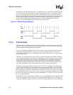
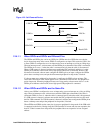
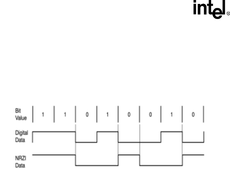
Figure 12-1 shows the NRZI encoding of the data byte 0b1101 0010.
12.3.3 Field Formats
Individual bits are assembled into groups called fields. Fields are used to construct packets and
packets are used to construct frames or transactions. There are seven USB field types: Sync, PID,
Address, Endpoint, Frame Number, Data, and CRC.
A Sync is preceded by the Idle state and is the first field of every packet. The first bit of a Sync
field signals the SOP to the UDC or host. A Sync is 8 bits wide and consists of seven zeros
followed by a one (0x80). Bits are transmitted to the bus least significant bit first in every field,
except the CRC field.
The PID is 1 byte wide and always follows the sync field. The first four bits contain an encoded
value that represents packet type (Token, Data, Handshake, and Special), packet format, and type
of error detection. The last four bits contain a check field that ensures the PID is transmitted
without errors. The check field is generated by performing a ones complement of the PID. The
UDC XORs the PID and CRC fields and takes the action prescribed in the USB standard if the
result does not contain all ones, which indicates an error has occurred in transmission.
The Address and Endpoint fields are used to access the UDC’s 16 endpoints. The Address field
contains seven bits and permits 127 unique devices to be placed on the USB. After the USB host
signals a reset, the UDC and all other devices are assigned the default address, zero. The host is
then responsible for assigning a unique address to each device on the bus. Addresses are assigned
in the enumeration process, one device at a time. After the host assigns the an address to the UDC,
the UDC only responds to transactions directed to that address. The Address field follows the PID
in every packet transmitted.
When the UDC detects a packet that is addressed to it, it uses the Endpoint field to determine which
of the UDC’s endpoints is being addressed. The Endpoint field contains four bits. Encodings for
endpoints 0 (0000b) through 15 (1111b) are allowed. The Endpoint field follows the Address field.
Figure 12-1. NRZI Bit Encoding Example


