Intel® PXA26x Processor Family Developer’s Manual 3-35
Clocks and Power Manager
3.6 Clocks Manager Registers
The clocks manager contains three registers:
• Core Clock Configuration Register (CCCR)
• Clock Enable Register (CKEN)
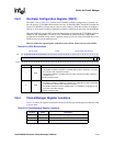
• Oscillator Configuration Register (OSCC)
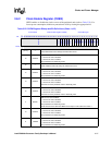
3.6.1 Core Clock Configuration Register (CCCR)
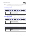
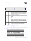
The CCCR controls the core clock frequency, from which the core, memory controller, LCD
controller, and DMA controller frequencies are derived. The crystal frequency to memory
frequency multiplier (L), memory frequency to run mode frequency multiplier (M), and run mode
frequency to turbo mode frequency multiplier (N) are set in this register. The clock frequencies are:
• Memory frequency = 3.6864 MHz crystal frequency * crystal frequency to memory frequency
multiplier (L)
• Run mode frequency = memory frequency * memory frequency to run mode frequency
multiplier (M)
• Turbo mode frequency = run mode frequency * run mode frequency to turbo mode frequency
multiplier (N)
The value for L is chosen based on external memory or LCD requirements and can be constant
while M and N change to allow run and turbo mode frequency changes without disrupting memory
settings. The value for M is chosen based on bus bandwidth requirements and minimum core
performance requirements. The value for N is chosen based on peak core performance
requirements.
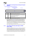
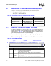
0x40F0 001C PCFR Power Manager General Configuration Register
0x40F0 0020 PGSR0 Power Manager GPIO Sleep State Register for GP[31-0]
0x40F0 0024 PGSR1 Power Manager GPIO Sleep State Register for GP[63-32]
0x40F0 0028 PGSR2 Power Manager GPIO Sleep State Register for GP[84-64]
0x40F0 0030 RCSR Reset Controller Status Register
0x40F0 0034 PMFWR Power Manager Fast Wake Up Configuration Register
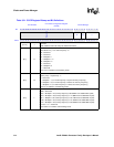
Table 3-20. Power Manager Register Locations (Sheet 2 of 2)
Address Name Description


