14-2 Intel® PXA26x Processor Family Developer’s Manual
Inter-Integrated Circuit Sound Controller
14.2 Signal Descriptions
SYSCLK is the clock on which all other clocks in the I
2
S unit are based. SYSCLK generates a
frequency between approximately 2 MHz and 12.2 MHz by dividing down the PLL clock with a
programmable divisor. This frequency is always 256 times the audio sampling frequency. SYSCLK
is driven out of the processor system only if BITCLK is configured as an output.
BITCLK supplies the serial audio bit rate, which is the basis for the external CODEC bit-sampling
logic. BITCLK is one-quarter the frequency of SYSCLK and is 64 times the audio sampling
frequency. One bit of the serial audio data sample is transmitted or received each BITCLK period.
A single serial audio sample comprises a “left” and “right” signal, each containing either 8, 16 or
32 bits.
SYNC is BITCLK divided by 64, resulting in an 8-KHz to 48-KHz signal. The state of SYNC is
used to denote whether the current serial data samples are “Left” or “Right” channel data.
The SDATA_IN and SDATA_OUT data pins are used to send/receive the serial audio data to/from
the CODEC.
Table 14-1 lists the signals between the I
2
S and an external CODEC device.
BITCLK can be configured either as an input or as an output. To program the direction, follow
these steps:
1. Program SYSUNIT’s GPIO Direction Register (GPDR). See Section 4.1.3.2, “GPIO Pin
Direction Registers (GPDR0, GPDR1, GPDR2)” on page 4-9 for details regarding the GPDR.
2. Program SYSUNIT’s GPIO Alternate Function Select Register (GAFR). See Section 4.1.3.6,
“GPIO Alternate Function Register (GAFR)” on page 4-17 for details regarding the GAFR.
3. Program the BCKD bit in the I2SC’s Serial Audio Control Register. See Section 14.6.1,
“Serial Audio Controller Global Control Register (SACR0)” for more details.
Note: Modifying the status of the SACR0[BCKD] bit during normal operation can cause jitter on the
BITCLK and can affect serial activity.
If BITCLK is an output, SYSCLK must be configured as an output. If BITCLK is supplied by the
CODEC, the GPIO pin GP32 can be used for an alternate function. To configure the pin as an
output, follow these steps:
1. Program SYSUNIT’s GPIO Direction Register (GPDR). See Section 4.1.3.2, “GPIO Pin
Direction Registers (GPDR0, GPDR1, GPDR2)” on page 4-9 for details regarding the GPDR.
2. Program SYSUNIT’s GPIO Alternate Function Select Register (GAFR). See Section 4.1.3.6,
“GPIO Alternate Function Register (GAFR)” on page 4-17 for details regarding the GAFR.
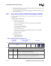
Table 14-1. External Interface to CODEC
Name Direction Description
GP32/SYSCLK O System Clock = BITCLK * 4 used by the CODEC only.
GP28/BITCLK I or O bit-rate clock = SYNC * 64
GP31/SYNC O Left/Right identifier
GP30/SDATA_OUT O Serial audio output data to CODEC
GP29/SDATA_IN I Serial audio input data from CODEC


