


9-6 Intel® PXA26x Processor Family Developer’s Manual
Inter-Integrated Circuit Bus Interface Unit
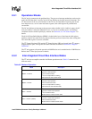
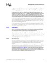
9.3.3.2 No START or STOP Condition
Use the no START or STOP condition (ICR[START]=0, ICR[STOP]=0) in master-transmit mode
while the I
2
C unit is transmitting multiple data bytes (see Figure 9-2). Software writes the data byte
and the I
2
C unit sets the ISR[ITE] bit and clears the ICR[TB] bit. The software then writes a new
byte to the IDBR and sets the ICR[TB] bit, which initiates the new byte transmission. This process
continues until the software sets the ICR[START] or ICR[STOP] bit. The ICR[START] and
ICR[STOP] bits are not automatically cleared by the I
2
C unit after the transmission of a START,
STOP, or repeated START.
After each byte transfer, including the ICR[ACKNAK] bit, the I
2
C unit holds the SCL line low to
insert wait states until the ICR[TB] bit is set. This action notifies the I
2
C unit to release the SCL
line and allow the next information transfer to proceed.
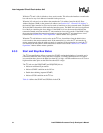
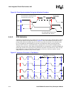
9.3.3.3 STOP Condition
The STOP condition (ICR[START]=X, ICR[STOP]=1) terminates a data transfer. In master-
transmit mode, the ICR[STOP] bit and the ICR[TB] bit must be set to initiate the last byte transfer
(see Figure 9-2). In master-receive mode, the I
2
C unit must set the ICR[ACKNAK] bit, the
ICR[STOP] bit, and the ICR[TB] bit to initiate the last transfer. Software must clear the
ICR[STOP] condition after it is transmitted.
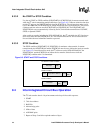
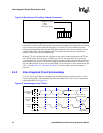
9.4 Inter-Integrated Circuit Bus Operation
The I
2
C unit transfers data in 1-byte increments and always follows this sequence:
1. START
2. 7-bit slave address
3. R/nW Bit
4. Acknowledge pulse
5. 8 Bits of data
6. ACK/NAK pulse
7. Repeat of Steps 5 and 6 for required number of bytes
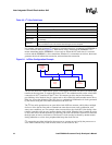
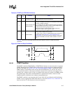
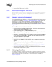
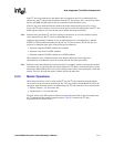
Figure 9-3. START and STOP Conditions
Data byte
ACK/
NAK
ACK/
NAK
R/nWSTART Target Slave Address
ACK/
NAK
Data Byte
STOP
No START or STOP Condition
START Condition
STOP Condition