Intel® PXA26x Processor Family Developer’s Manual 13-5
AC97 Controller Unit
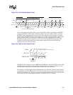
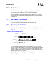
A new audio output frame begins with a low-to-high SYNC transition synchronous to BITCLK’s
rising edge. BITCLK’s falling edge immediately follows and AC97 samples SYNC’s assertion.
BITCLK’s falling edge marks the instance that AC-link’s sides are each aware that a new audio
frame has started. On BITCLK’s next rising edge, the ACUNIT transitions SDATA_OUT into the
slot 0’s first bit position (valid frame bit). Each new bit position is presented to AC-link on a
BITCLK rising edge and then sampled by AC97 on the following BITCLK falling edge. This
sequence ensures that data transitions and subsequent sample points for both incoming and
outgoing data streams are time aligned.
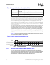
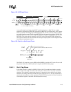
The SDATA_OUT composite stream is MSB-justified (MSB first). The ACUNIT fills all non-valid
slot bit positions with zeroes. If fewer than 20 valid bits exist in an assigned valid time slot, the
ACUNIT stuffs all trailing non-valid bit positions of the 20-bit slot with zeroes.
For example, if a 16-bit sample stream is being played to an AC97 DAC, the first 16 bit positions
are presented to the DAC MSB-justified. They are followed by the next four bit positions that the
ACUNIT stuffs with zeroes. This process ensures that the least significant bits do not introduce any
DC biasing, regardless of the implemented DAC’s resolution (16-, 18-, or 20-bit).
Figure 13-3. AC-link Audio Output Frame
SYNC
BIT_CLK
SDATA_OUT
slot(1)
Time Slot "Valid"
Bits
20.8uS
(48 KHz)
Slot 1
Slot 2
0 19 0 19 0
19 0
Slot 3
Slot 12
81.4 nS
12.288 MHz
slot(2)
codec IDcodec ID
"0"slot(12)
("1" = time slot contains valid PCM data)
19
Valid
Frame
End of previous
Audio Frame
Tag Phase Data Phase
Figure 13-4. Start of Audio Output Frame
SYNC
SDATA_OUT
slot(1) slot(2)
Valid
Frame
End of previous
Audio Frame
AC '97 samples SYNC assertion here
AC '97 samples first SDATA_OUT bit of frame here
BIT_CLK


