Intel® PXA26x Processor Family Developer’s Manual 13-9
AC97 Controller Unit
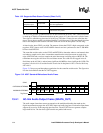
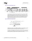
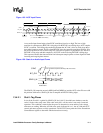
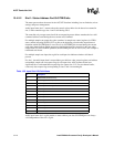
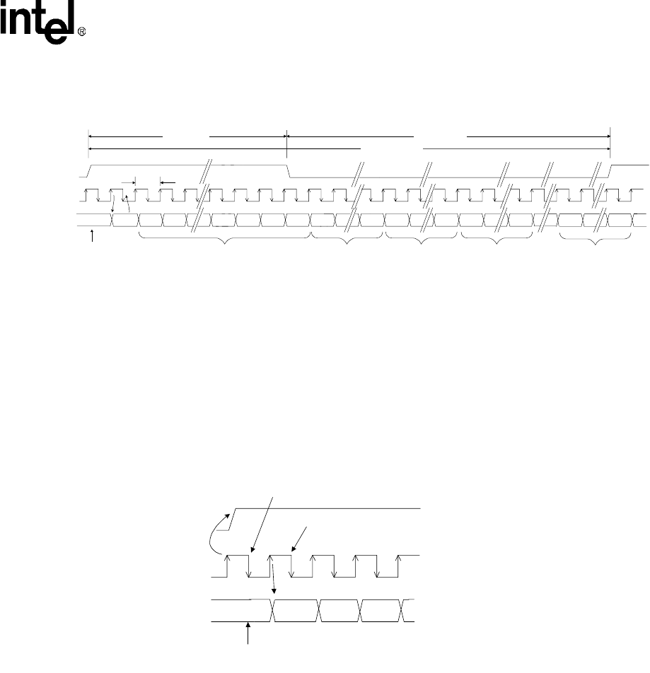
A new audio input frame begins when SYNC transitions from low to high. The low to high
transition is synchronous to BITCLK’s rising edge. On BITCLK’s next falling edge, AC97 samples
SYNC’s assertion. This falling edge marks the moment that AC-link’s sides are each aware that a
new audio frame has started. The next time BITCLK rises, the controller transitions SDATA_IN to
the first bit position in slot 0 (codec ready bit). Each new bit position is presented to AC-link on a
BITCLK’s rising edge and then sampled by ACUNIT on the following BITCLK’s falling edge.
This sequence ensures that data transitions and subsequent sample points are time aligned for both
incoming and outgoing data streams.
The SDATA_IN composite stream is MSB justified (MSB first) and the AC97 codec fills non-valid
bit positions with zeroes. SDATA_IN data is sampled on BITCLK falling edges.
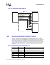
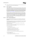
13.4.2.1 Slot 0: Tag Phase
In slot 0, the first bit is a global bit (SDATA_IN slot 0, bit 15) that indicates whether or not the
codec is in the codec ready state. If the codec ready bit is a 0, the codec is not ready for normal
operation. This condition is normal after the power is deasserted on reset and the codec voltage
references are settling. When the AC-link codec ready indicator bit is a 1, the AC-link and AC97
control and status registers are fully operational. The ACUNIT must probe the Codec Powerdown
Control/Status register to determine which subsections are ready.
Figure 13-5. AC97 Input Frame
SYNC
BIT_CLK
SDATA_IN
slot(1)
Time Slot "Valid"
Bits
20.8uS
(48 KHz)
Slot 1
Slot 2
0 19 0 19 0
19 0
Slot 3
Slot 12
81.4 nS
12.288 MHz
slot(2) "0""0""0"slot(12)
("1" = time slot contains valid PCM data)
19
Codec
Ready
End of previous
Audio Frame
Tag Phase Data Phase
Figure 13-6. Start of an Audio Input Frame
SYNC
SDATA_IN
slot(1) slot(2)
Codec
Ready
End of previous
Audio Frame
AC '97 samples SYNC assertion here
AC '97 Controller samples first SDATA_IN bit of frame here
BIT_CLK


