


7-36 Intel® PXA26x Processor Family Developer’s Manual
Liquid Crystal Display Controller
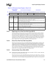
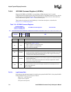
7.6.4.7 AC Bias Pin Transitions Per Interrupt (API)
The 4-bit API field specifies the number of AC bias pin (L_BIAS) transitions to count before
setting the LCSR[ACS] status bit that signals an interrupt request. After the LCD controller is
enabled, the value in API is loaded to a 4-bit down counter, and the counter decrements each time
L_BIAS is inverted. When the counter reaches zero, it stops, and the LCSR[ABC] count bit is set.
Once LCSR[ABC] is set, the 4-bit down counter is reloaded with the value in API and is disabled
until ABC is cleared. When ABC is cleared by the CPU, the down counter is enabled and again
decrements each time the AC bias pin is inverted. The number of AC bias pin transitions between
each interrupt request ranges from 1 to 15. Setting API to 0x0 disables the API function.
In active display mode (LCCR0[PAS]=1), L_BIAS is the output enable signal. However, signalling
of the API interrupt may still occur. The ACB bit field can be used to count line clock pulses in
active mode. When the programmed number of line clock pulses occurs, an internal signal is
toggled that decrements the 4-bit counter used by the API interrupt logic. Once this internal signal
toggles the programmed number of times, as specified by API, an interrupt is generated. The user
must program API to zero if the API interrupt function is not required in active mode.
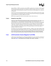
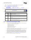
7.6.4.8 AC Bias Pin Frequency (ACB)
In passive display mode (LCCR0[PAS]=1), the 8-bit ACB field specifies the number of line clocks
to count between each toggle of the AC bias pin (L_BIAS). After the LCD controller is enabled,
the value in ACB is loaded to an 8-bit down counter, which begins to decrement using the line
clock (L_LCLK). When the counter reaches zero, it stops, L_BIAS is toggled, and the whole
procedure starts again. The number of line clocks between each bias pin transition ranges from 1 to
256, corresponding to ACB values from 0 to 255. Thus, the value to program into ACB is the
desired number of line clocks minus 1.
A passive LCD display uses AC bias to periodically reverse the polarity of the power supplied to
the screen in order to eliminate D.C. offset. If the LCD display being controlled has its own internal
means of switching its power supply, set ACB to its maximum value (0xFF) to reduce power
consumption. ACB must be programmed conservatively in a system with bandwidth problems that
result in output FIFO underruns in the LCD controller. In these cases, the pixel clock is stalled for
passive displays, which can result in more time between line clocks than expected. See
Section 7.3.5, “Liquid Crystal Display Controller Pin Usage” on page 7-9 for more information on
how output FIFO underruns are handled.
In active display mode, the ACB bit field has no effect on the L_BIAS pin. Because the pixel clock
toggles continuously in active mode, the AC bias pin is used as an output enable signal. In active
mode, it is asserted automatically by the LCD controller whenever pixel data is driven to the data
pins. This signals the display when it may use the pixel clock to latch pixels. Use ACB in active
mode to count line clocks and generate API interrupts.
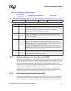
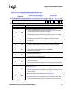
7.6.4.9 Pixel Clock Divider (PCD)
The 8-bit PCD field selects the frequency of the pixel clock (L_CLK). PCD can be any value from
0 to 255. It generates a range of pixel clock frequencies from LCLK/2 to LCLK/512, where LCLK
is the programmed frequency of the LCD/memory controller clock. LCLK can vary from 100 MHz
to 166 MHz.
The pixel clock frequency must be adjusted to meet the required screen refresh rate, which depends
on:
• Number of pixels for the target display